About the LK-G5000
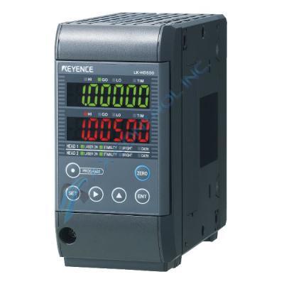
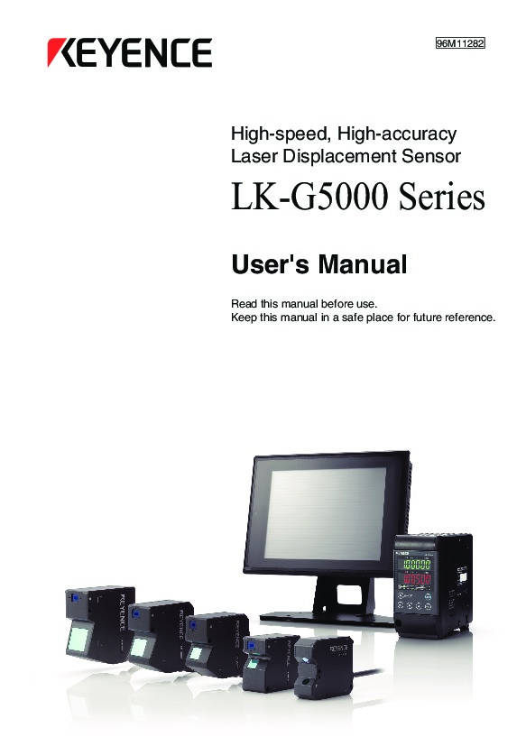
The LK-G5000 system configuration is manufactured by Keyence. This system configuration centers around an LK-G5000 controller. A sensor head expansion unit may be attached to the controller so that the controller may support up to 12 sensor heads. The CC-link communication unit, the DeviceNet communication unit, and a dedicated touch panel can be attached to the controller to add additional functionality. Additional options include the photoelectric sensor and proximity sensor, the recorder, the programmable logic controller (PLC), the indicator and buzzer, and a PC (via the RS-232C communication port or the parallel I/O board of the PC). The controller includes display panel housing, comparator output indicators, a TIM (synchronous input) indicator, a measured value display, sensor head status indicators (LASER ON, STABILITY, BRIGHT, DARK), operation keys (PROGRAM, SET, ENT, ZERO, right/up arrow keys), and a display panel fixing screws.
The 12-pin terminal block includes 12 terminals. COM_IN (Terminal 12) is the COM for input, REMOTE (Terminal 11) is the laser remote interlock input, ZERO1 (Terminal 10) is the auto-zero (synchronous) input, RESET1 (Terminal 9) is the reset (synchronous) input, TIMING1 (Terminal 8) is the TIMING (synchronous) input, COM_OUT (Terminal 7) is the COM for output, GO (Terminal 6) is the general comparator output, ALARM (Terminal 5) is the system alarm or measured value alarm, LASER_CTRL1 (Terminal 4) is the laser control input 1, LASER_CTRL2 (Terminal 3) is the laser control input 2, 24 VDC (+) (Terminal 2) is the 24 VDC input for the power supply, and 24 VDC (-) (Terminal 1) is the 0 V input for the power supply.
For additional information about this unit, especially specific information regarding installation procedures, please refer to Keyence manuals and user guides. These will provide you with specific and step-by-step information.


