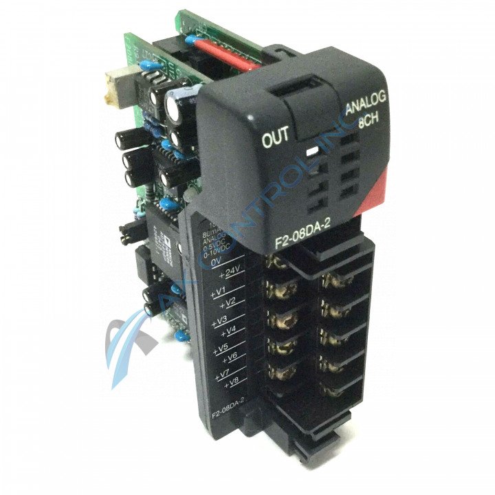
About the F2-08DA-2
To increase the reliability and usability of the F2-08DA-2 Analog Output Voltage Module, the device has important hardware features.
-
The module optically isolates outputs from the PLC to improve signal quality.
-
For improved usability and portability, the terminal block is easily removable to ensure the F2-08DA-2 Analog Output Voltage Module is easily removable without disconnecting wiring.
-
If a DL240, DL250-1 or a DL260 CPU is used all channels can be updated in one scan.
The F2-08DA-2 Analog Output Voltage Module is a 8 channel analog Output Voltage Module. The output range is 0–5V, 0–10V. The peak output voltage is 15 VDC (clamped by transient voltage suppressor). The resolution is 12 bit (1 in 4096). The power budget requirement is 60mA @ 5 VDC (supplied by the base). The environmental air requirement is no corrosive gases permitted. The operating temperature 0–60°C (32–140°F). The relative humidity 5–95% (non-condensing).
Jumpers on the The F2-08DA-2 Analog Output module are used to select the voltage ranges for each channel. The PLC update rate is 1 channel per scan maximum (multiplexing) 8 channels per scan maximum (pointer – DL240, DL250-1, and DL260 only).
The output points required is 12 binary data bits, 3 channel ID bits, 1 output enable bit / 16 (Y) output points required.
When wiring the F2-08DA-2 Analog Output Voltage Module, consider the following information.
-
Use the shortest wiring route.
-
Be sure to use shielded wiring and ground the shield at the transmitter source.
-
To avoid electrical noise, keep away from large motors, high current switches and transformers when planning the wiring route.
-
To avoid damage, route the wires through approved cable housing only. Follow all applicable codes to select the correct housing.


