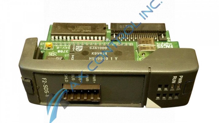
About the F2-SDS-1
The F2-SDS-1 Smart Distributed System Module contains 2 status indicators.
PWR is lit when when power is ON.
RUN indicates several conditions:
-
RUN is lit when the module completes all internal diagnostics.
-
RUN flashes once per second when the module is connected to an SDS network and is communicating with the SDS master.
-
RUN is lit when power is on and the module is not connected to a SDS network.
-
RUN flashes very rapidly when the power on diagnostics has failed.
The communication to field devices is over a standard 4-wire shielded cable to cabinet connector, molded 4-wire cable at up to 1Mbps to field devices. The module connector is a 5-position removable terminal (European style). The operating environment is 0ºC to 60ºC (32ºF to 140ºF), 5% to 95% humidity (non-condensing).
You can install the F2-SDS-1 in the CPU slot of any DL205 base. Also, the number of I/O is determined by the number of I/O slots per base. The internal power consumption is 160 mA at 5VDC. The maximum SDS addresses per CPU is 8 discrete, 64 analog. The maximum number of field devices per bus is
Consider that the F2-SDS-1 Smart Distributed System Module supports all discrete (except 32-pt.) and analog I/O modules. Specialty modules are not supported by the F2-SDS-1 module.


