About the ISM1410-01
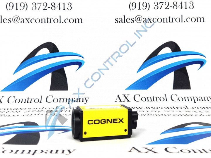
The ISM1410-01 model was designed to be used as a compact vision system. As a compact and stand-alone vision system, it can be used in hard-to-reach places. The way this model can be mounted allows for it to be adjusted at a forty-five-degree angle.
The are numerous different wires and cables that are associated when connecting the ISM1410-01 model to different connector types. For example, when connecting the power supply it should first be noted that the chosen I/O module should never be connected to a power source that is greater than 24 VDC. Connecting it to a higher voltage can cause shock or even fire which will damage the hardware. When a power source has been secured a screwdriver should be used to loosen the I/O’s power terminals, once the terminals have been loosened insert the 24 VDC positive and negative wires in the 24 VDC positive and negative terminals on the I/O module, finally, the screw terminals should be tightened to secure the wire leads.
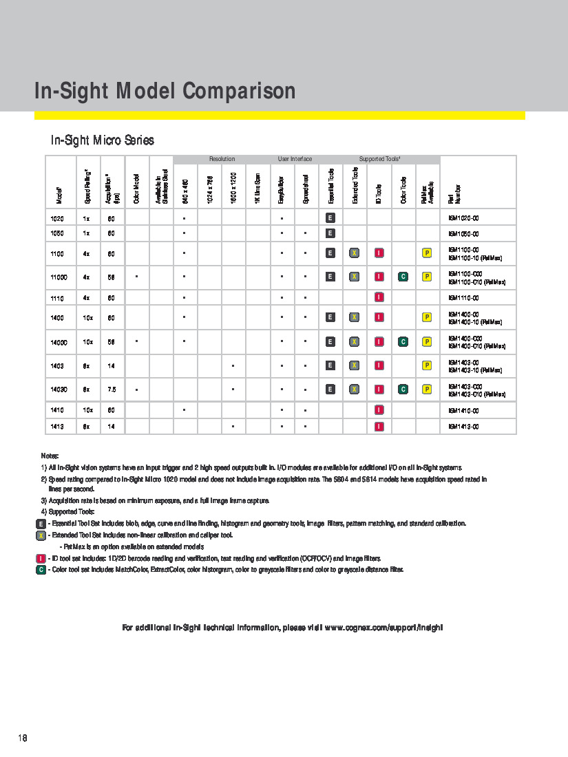
There are a variety of specifications that came with the ISM1410-01 model which include but are not limited to the sensor type, minimum firmware, maximum pixels, bit depth, and several others. All of the named specifications are as follows:
-
Bit Depth: 256 Grey Levels
-
Minimum Firmware: In-Sight Version 4.4.3
-
Maximum Pixels (Resolution): 640 x 480
-
Sensor Type: ⅓” CCD
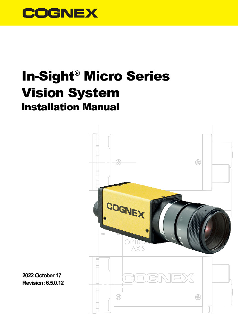
For even more specifications regarding this model refer to pages eighteen through twenty in the In-Sight Micro Series Vision System Installation Manual.


