About the 193X741ACG01
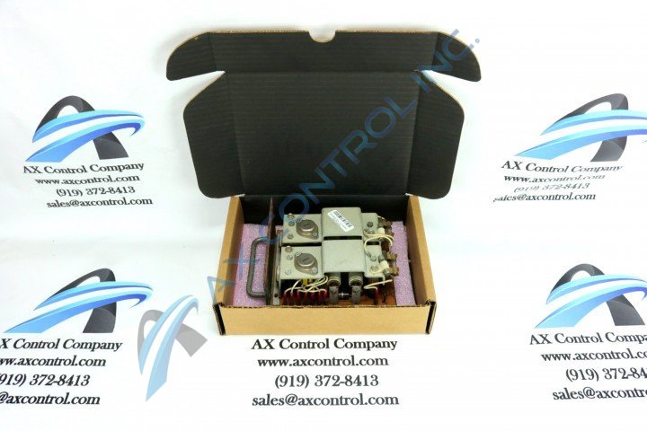
The 193X741ACG01 is a printed circuit board designed to fit into GE drives. This board functions as a Power Supply Dual Output board. The board is marked as such on its surface.
The 193X741ACG01 has a silver colored front panel with a blue band. This panel is printed with the board id number, the card information/name, and the GE logo. The panel has a rounded front handle attached at two points. This panel attaches using two screws to the bottom of the PCB.
The 193X741ACG01 has a bottom board that carries the board components. This board is brown in color and has silver colored traces. When looking at the bottom of this PCB, one can see the code 942B269BC and many of the through-hole soldering points along the silver traces. There are also several screw mounts that have been used to attach larger components to the board.
The 193X741ACG01 has two large metal flanges that parallel the board and connect via metal supports. Most components on the 193X741ACG01 are below these flanges. However, there are two large transistors attached to the top of these components, and four fuses attached to one side. Surface wiring extends from below these flanges out to the surface of the board from both open sides. These wires attach to labeled points that are marked T, Q, R, E, B, C, and S1 and S2. Surface wiring also attaches to two points on the top of the flanges.
The 193X741ACG01 has four large aluminum electrolytic capacitors that are each attached to flat metal posts that allow them to be placed above the surface of the board. The board also has polyester vinyl and smaller aluminum electrolytic capacitors that connect directly to the board. Resistors tend to be either carbon composite or metal film, and are usually mounted horizontally.
Technical support from GE publications like manuals and data sheets may be the best resource for installation instructions and safety data.


