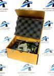
About the 193X741ACG03
The 193X741ACG03 is a GE circuit board designed for GE drives. This board functions as a power supply board.
The 193X741ACG03 is built with a bottom board that carries all components. This board is brown in color and is marked with the board ID number, the code 942B269BC, -A, T127, and component numbers and designators. It is also labeled as a “Power Supply Output.” The bottom of the board shows the traces and the through-hole soldering, as well as several screw mounts used to connect larger components.
The 193X741ACG03 is built with two large metal flanges connected to the board by metal vertical connectors. These flanges rest over the top of the board and protect most of the components on its surface. Above these flanges, attached to their top, are two large transistors. There are four fuses also attached to the side of the flanges. Two are connected using plastic strapping, and two are connected using brass connectors. Surface wiring attaches to the top of the flanges next to two of these fuses, connecting via two screws. Several surface wire connections extend from the underside of the flanges and connect to the board in a single line on either side of the board. These connections are labeled T/Q/R/E/B/C/S1 and S2.
The board uses aluminum electrolytic capacitors. Four large a.c. capacitors are mounted to tall, flat metal posts, which allow the capacitors to hover above the board. The board also uses other capacitors that connect directly to the board via through-wires. The board uses carbon composite and metal film resistors. These resistors may be connected to the board in either a horizontal or a vertical position.
Manuals or data sheets for the 193X741ACG03 were published by GE, and are excellent resources for safety data and installation instructions.


