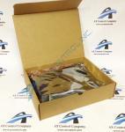
About the 531X171TMAABG2
The GE Terminal Board Relay Card 531X171TMAABG2 contains interface circuitry and the connection terminals for most signal I/O. The board connects to the drive control board through cables. The GE Terminal Board Relay Card 531X171TMAABG2 contains a terminal block that requires your consideration before you attempt to connect wires to it. The terminal block is used to secure individual wires used to send and receive control signals. Each wire is secured to the terminal block with a small screw.
To attach a wire to the terminal block, loosen the screw with a screwdriver but do not remove the screw. Insert the wire into the terminal and make sure it is completely engaged in the connector. Use the screwdriver to tighten the screw and secure the wire in the terminal block. Tug on the wire to test the connection.
The GE Terminal Board Relay Card 531X171TMAABG2 is secured inside the drive cabinet with four screws. First, remove all power to the drive and wait a few seconds for all power to drain from the board. Some components of the board hold voltage for a few seconds after power is removed so to avoid personal injury, it is important to allow time for all power to drain off.
Loosen the four screws to remove the defective board. However, make sure the screwdriver does not touch any components inside the drive. Before you remove any cables attached to the board, note where they are connected and label each cable with the identifier of the connector.


