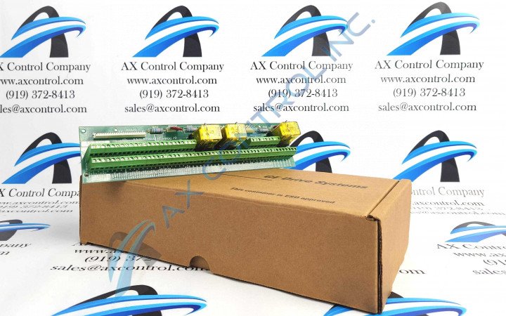
About the 531X171TMAAEG2
The GE Terminal Board Relay Card 531X171TMAAEG2 contains interface circuitry and the connection terminals for most signal I/O. The board connects to the drive control board through cables.
The GE Terminal Board Relay Card 531X171TMAAEG2 features several connectors for cables that connect the board to components in the drive. Before you start the replacement, inspect the defective board and note all wires and cables connected to it. The board features a terminal on which multiple single wires are connected that provide for electrical signals that are sent to other components in the drive. It also provides for signals that are sent to the board for processing. Create labels that provide information concerning where the wires are connected on the terminal. This will avoid the possibility of wiring the replacement board incorrectly which would lead to further down time for the drive.
To remove the wires from the terminal, create the label and apply it to the wire. Each terminal has a separate connector that is held in place with a screw. Use a screwdriver to loosen the screw that holds the wire in place. Remove the wire from the terminal and move it to one side while the new board is installed in the drive. To install the wire in the new board, use a screwdriver to loosen the screw and insert the wire in the connector. Make sure the bare metal is in the connector. Tighten the connector with the screwdriver.


