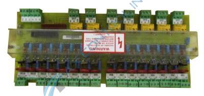
531X213D10AAG1

    Varying star amount pictures Varying star amount pictures Varying star amount pictures Varying star amount pictures Varying star amount pictures
  • 5.00 (3)
  • Click a star to rate this product
    Varying star amount pictures Varying star amount pictures Varying star amount pictures Varying star amount pictures Varying star amount pictures
  • 5.00 (3)
  • Click a star to rate this product
GE Input/Output Board

AVAILABILITY:

IN STOCK
SHIPS IN 3-5 DAYS

Sell Surplus: Have a 531X213D10AAG1 to sell? Sell Now
Exchange Credit: Learn more about our exchange credit program
  • Part Number: 531X213D10AAG1
  • SKU: 531X213D10AAG1GBTC
  • Manufacturer: GE Boards & Turbine Control
  • Series: 531x Boards

About the 531X213D10AAG1

The 531X213D10AAG1 is an I/O circuit board. The 531X213D10AAG1 has sixteen small microchips. Microchips are used to store information for the 531X213D10AAG1 to function. The 531X213D10AAG1 features sixteen transistors. These transistors are placed at the base of three opening female terminal ports. There are sixteen female ports along one edge and nine female ports along the other edge. The sixteen on the bottom edge are labeled as such. Each piece has a negative and positive symbol along with IN1, IN2, IN3, IN4, IN5, IN6, IN7, IN8, IN9, IN10, IN11, IN12, IN13, IN14, IN15, IN16. Each piece has three small silver screws that connect wires to the circuit board. There are sixteen red circular capacitors (condensers) in front of each female port. There are twenty-nine blue capacitors as well that separate the red capacitors and transformers. On the top edge of the circuit board the nine female ports are labeled OT1 (NO, NC, COM), OT2 (NO, NC, COM), OT3 (NO, NC, COM), OT4 (NO, NC, COM), OT5 (NO, NC, COM), OT6 (NO, NC, COM), OT7 (NO, NC, COM). The other two are labeled 11, 12, 13, 14. The 531X213D10AAG1 has two metal male prongs to attach to the surrounding circuit boards. The 531X213D10AAG1 has seven yellow squares. The 531X213D10AAG1 has a clear plastic case that goes down the center of the circuit board with a sticker on the top. The sticker reads “WARNING Hazard of Electrical Shock or Burn…Disconnect All Power Before Servicing This Equipment.”

If you’d like a quote please call or email AX Control.

Repair Services For 531X213D10AAG1

Type Lead Time Price Action
Repair Service 1-2 weeks $353

Our highly skilled technicians can repair your 531X213D10AAG1. All of our repairs come with a 3 Year AX Control Warranty. Please contact us for additional information about our repair process. To receive the repair pricing and lead time listed above please process your repair order via our website. The following repair options may be available upon request:

  • 48-72hr Rush Repair
  • Detailed Repair Reports
  • AX Control Certificate of Warranty

AX Control Warranty Info

All products we sell are backed by our unparalleled warranty. A warranty certificate will be provided with your order upon request.
All PLCs, HMIs, and Turbine Control Boards: 3 Years
All AC/DC and Servo Drives: 2 Years
All Motors: 1 Year
Learn More

531X213D10AAG1 Manuals, White Papers, Data Sheets, and Troubleshooting