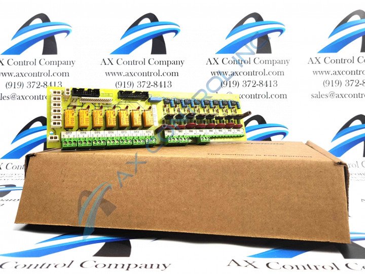
About the 531X307LTBAFG1
The 531X307LTBAFG1 functions as a LAN Terminal board. It is typically installed within the drive or exciter cabinet. The terminal board is used to create interfaces between drives, exciters, or other control devices and connected external devices like interlocks, pushbuttons, contactors, or indicator lights.
There are two versions of this board. The G1 LTB is built with eight 24VDC input plugs as compared to the G2 LTB board that does not have these inputs available and instead uses dc input signals from connector terminals.
The 531X307LTBAFG1 is designed with three terminal strips located along one long edge. Along the opposite edge, the board has two male vertical pin connectors along with the previously mentioned input plugs. The board also has a long line of LED indicators that spans the long dimension of the board. There are 15 LED indicators in all. Other board components include transistors, seven relays, multiple metal oxide varistors, along with resistors, diodes, and capacitors. The board is marked with the GE logo and with the board ID number, as well as carrying a barcode near its center. Additionally, individual components are marked with reference designations.
It is important to note that any board replacement should begin by turning off power to the board. This is to prevent any chance of electric shock, as well as to prevent possible damage to the drive or other equipment.
For more information regarding proper installation and removal procedures, or for information about board components, please review original documentation from General Electric like manuals and user guides.


