IS200EDCFG1A

    Varying star amount pictures Varying star amount pictures Varying star amount pictures Varying star amount pictures Varying star amount pictures
  • 5.00 (5)
  • Click a star to rate this product
    Varying star amount pictures Varying star amount pictures Varying star amount pictures Varying star amount pictures Varying star amount pictures
  • 5.00 (5)
  • Click a star to rate this product
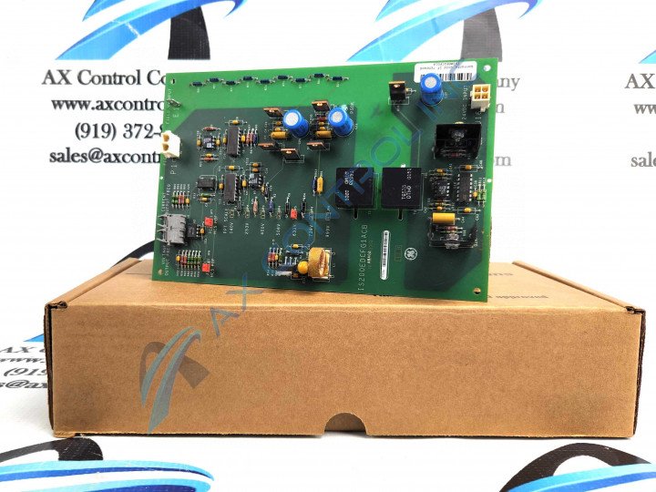
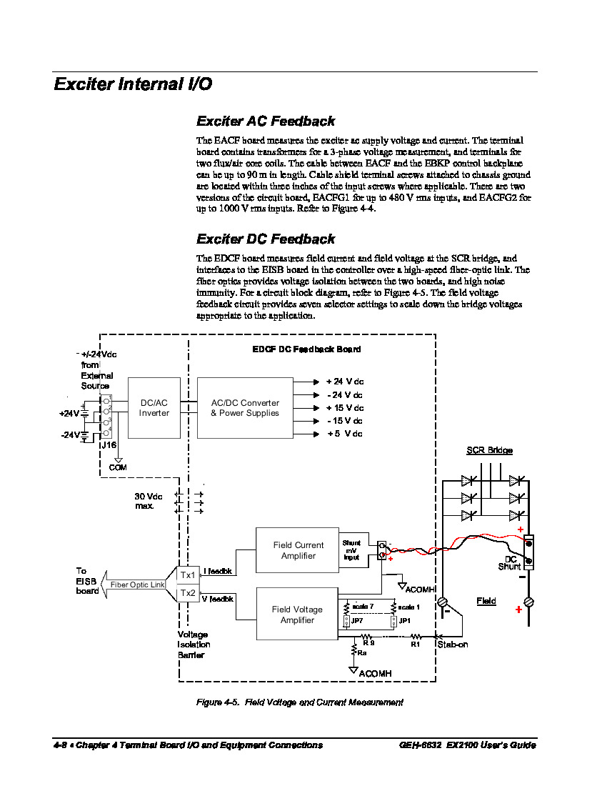
Controller Exciter DC Feedback Board part IS200EDCFG1A measures field voltages and currents at the SCR bridge of the device, currents are measured by dc shunts in field currents, this also has an EISB board for a high-speed fiber optic link.

AVAILABILITY:

IN STOCK
SHIPS TODAY

Sell Surplus: Have a IS200EDCFG1A to sell? Sell Now
Exchange Credit: Learn more about our exchange credit program
  • Part Number: IS200EDCFG1A
  • SKU: IS200EDCFG1AGBTC
  • Manufacturer: GE Industrial Systems
  • Series: EX2100 Excitation Control

IS200EDCFG1A Technical Specifications

Board Description Exciter DC Feedback
Board Type Input/Output Terminal Board
External Power Supply ±24 VDC
Functional Acronym/Abbreviation EDCF
Hardware Form A, Not Backward Compatible
Manual GEI-100464

About the IS200EDCFG1A

Part number IS200EDCFG1A is part of the EX2100 Excitation Controller Series. This model is an exciter direct current feedback board, which measures field voltage and field current at the SCR bridge. To properly use this model it is necessary to connect it to the EISB board when done so two fiber-optic cables are used for one signal each. The two fiber-optic cables that can be used are plastic fiber, the plastic fiber cable is used for distances up to ten meters; and a hard-clad silica fiber cable, this cable is used for distances up to ninety meters. Please note that the minimum bending radius of these cables is each one and a half inches. 

The field voltage feedback of the IS200EDCFG1A will always be measured across the negative terminal of the bridge device and across the positive terminal of the shunt. When the voltages have been scaled alongside the jumpered resisters the signals will proceed to be input to a different amplifier, this amplifier controls the VCO. 

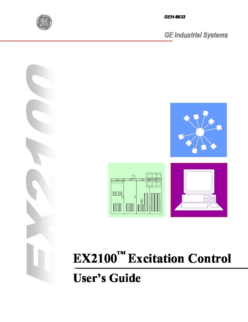
There are two manuals that can be used with the IS200EDCFG1A model, one of them is the general GEH-6632 EX2100 Excitation Control User’s Guide and the other is the GEI-100464 Exciter DC Feedback Board manual. 

Frequently Asked Questions about IS200EDCFG1A

The IS200EDCFG1A board has a two-pin J16 connector, what are the two pins on the connector used for?

The two pins on the J-16 connector are both used for external VDC voltages. Pine one is a positive twenty-four VDC input to the DC-DC convertor. Pin two is also twenty-four VDC, but is a common input to the DC-DC converter. 

What are the descriptions for the two fiber-optic connectors on the IS200EDCFG1A board?

The fiber-optic connectors are labeled CF OF and VF OF. The CF OF connector is a field current feedback pulse, HFBR-1528 fiber-optic driver/connector. The VF OF current is a field voltage feedback pulse, HFBR-1528 fiber-optic driver/connector. 

There is one LED indicator on the IS200EDCFG1A board. What does this LED indicate?

The one LED on the IS200EDCFG1A board will light up green and indicate the power supply is operating. The LED is also labeled PSOK. 

The IS200EDCFG1A measures field voltages across terminals, after these voltages, have been measured what happens to them?

After the field voltages have been measured there are scared with jumpered resistors. The signals are then input to different amplifiers that control the VCO (voltage-controlled oscillator).

Reviews For IS200EDCFG1A

Internal Review
(5.0)

The IS200EDCFG1A model has one LED light located on the front of the board, if this LED goes out it can be easily replaced. - AX Control Tech Team

Repair Services For IS200EDCFG1A

Type Lead Time Price Action
Repair Service 1-2 weeks $1245

Our highly skilled technicians can repair your IS200EDCFG1A. All of our repairs come with a 3 Year AX Control Warranty. Please contact us for additional information about our repair process. To receive the repair pricing and lead time listed above please process your repair order via our website. The following repair options may be available upon request:

  • 48-72hr Rush Repair
  • Detailed Repair Reports
  • AX Control Certificate of Warranty

AX Control Warranty Info

All products we sell are backed by our unparalleled warranty. A warranty certificate will be provided with your order upon request.
All PLCs, HMIs, and Turbine Control Boards: 3 Years
All AC/DC and Servo Drives: 2 Years
All Motors: 1 Year
Learn More