Frequently Asked Questions about DS200DDTBG1A
What is a DS200DDTBG1A Terminal Board?
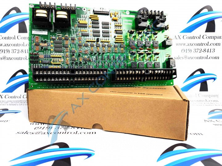
The DS200DDTBG1A is a LCI Auxiliary I/O Terminal Board that is used GE LS2100 Control Systems.
What manual is best used to help operate and install the DS200DDTBG1A board?
There is a parts-specific manual labeled as the GEI-100219 LCI Auxiliary I/O Terminal Board that can help with the operation and installation needs and a series manual labeled as the GEH-6373 Load Commutated Inverter User's Manual. Both of these manuals can be found attached within the Manuals tab above.
Where is the power for the DS200DDTBG1A board derived from?
The power for the DS200DDTBG1A board is provided from the attached ADMA board.
The DS200DDTBG1A board has high voltage AC inputs, high current signal inputs, low current signal inputs, and 4-20 mA current loop inputs, but undedicated voltage inputs as well. What are the undedicated voltage inputs?
The undedicated voltage inputs are inputs that are provided through a differential input voltage amplifier that feeds an analog VCO input to the ADMA board. The makeup of this these inputs are screw-type terminal blocks and are protected from voltage surges.
There are 12 jumpers on the DS200DDTBG1A board what are these jumpers used for?
The purpose of the jumpers is to reassign the LEM and CT input channels to become inputs for 4-20 mA current loop signals.
There are four voltage outputs on the DS200DDTBG1A board, what are these outputs, and what is their makeup?
The four voltage outputs on the DDTB board are buffered analog outputs which are available at screw terminals. Each output has a 200-ohm series resistor that allows for the isolation of the amplifier from the customer connection. Included in the buffer outputs is a gain of two that provides a ±10 V output range from the ±5 V from the attached ADMA board.


