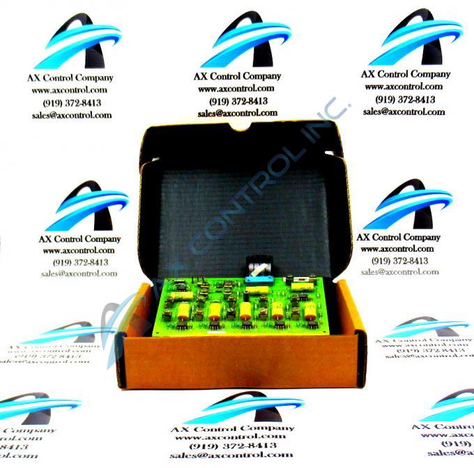
About the DS3800DADB1A1A
The GE Gas Turbine Control Board DS3800DADB1A1A features one 20-pin ribbon cable permanently attached to the board and 3 pin-type connectors. The GE Gas Turbine Control Board DS3800DADB1A1A also is populated with terminals for attaching a variety of components. The terminals on the board provide you with great versatility when installing the board. Without the need to modify the board or solder new components on the board, you can add components to the terminals that will change the processing performed by the board.
To add a component, use a screwdriver to loosen the screws on top of the two terminals between which you will add the component. Use the information provided with the board from the manufacturer for a description of the use of the terminals. Then, slide the lead wires in the terminals. Tighten the terminals when you are ready. The components can be removed or replaced at a later date, if necessary. Make sure the individual who is adding components to the board has a good understanding about the board and how the addition of the components will change the operation of the board.
Another way to change the operation of the board is to configure the board using the jumpers. The 3-pin jumpers each has 2 positions. One position is when the jumper covers pins 1 and 2. The other position is when the jumper covers pins 2 and 3. The information supplied by the factory describes how the jumper settings change the processing of the board. Each jumper has a default position. It is the position the jumper is set for when the board comes from the factory.


