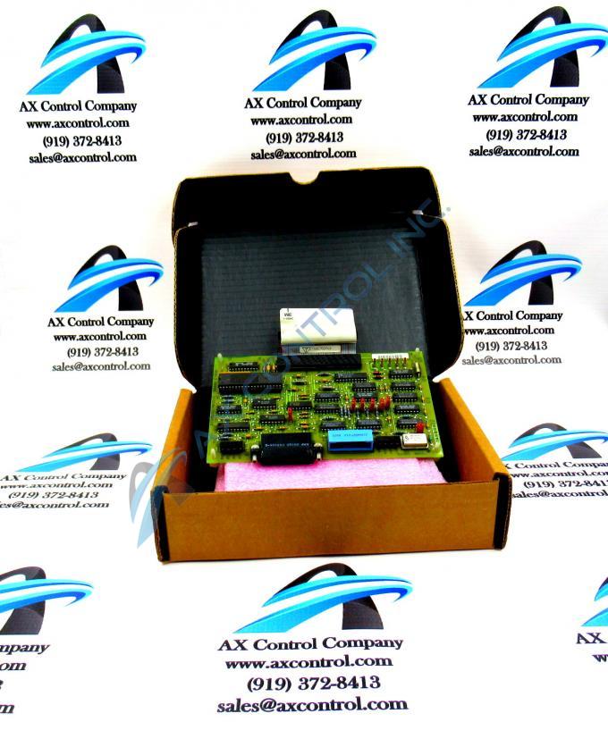
About the DS3800DCMB1C1B
The GE Printed Circuit Board DS3800DCMB1C1B features 1 40-pin connector and multiple EPROM modules. It also is populated with 4 indicator LEDs, 7 jumpers, and 1 20-pin connector. The ID of the jumpers are suffixed with JP and end with a one-digit number. For example, JP1, JP4, and JP9 are IDs of 3 jumpers. When you replace the board use the IDs to move the jumpers on the replacement board to match the positions on the old board.
There are some important factors to consider when you replace the board relating to the jumpers. When the original board is received from the factory and installed in the drive, the jumpers are set to configure the board for use at the site. Best practice is to review the configuration options with the engineers, management, and operators at the site and decide on the configuration settings to use. Place the board on a clean desk or workbench and use a wrist strap to guard against static buildup. Set the jumpers as required by the site.
The default setting is the position of the jumper when the board is received from the factory. It is the most common setting used for the jumper. The 3-pin jumpers have only 2 valid positions. One position is when the jumper covers pins 1 and 2. The other position is when the jumper covers pins 2 and 3. To move the jumper pull the jumper from the pins it covers. Then, align the jumper with the appropriate pins and press the jumper over the pins. The jumper make a signal connection between the 2 pins it covers.


