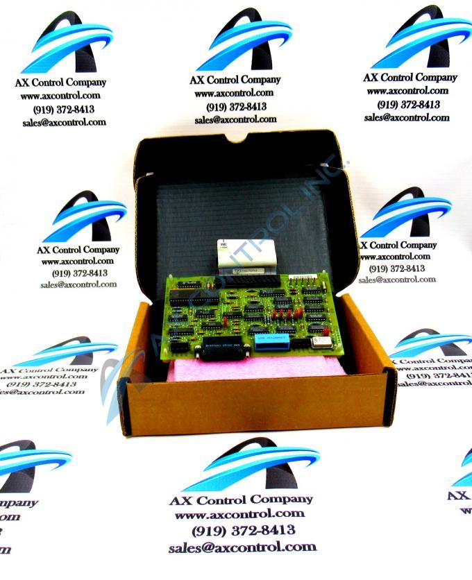
About the DS3800DCMB1D1B
The GE Printed Circuit Board DS3800DCMB1D1B features 1 40-pin connector and multiple EPROM modules. It also is populated with 4 indicator LEDs, 7 jumpers, and 1 20-pin connector.
The LEDs indicate processing activity on the board. One LED is assigned the ID TXDA and it flashes when the board is transmitting signals. One LED is assigned RXDA and it flashes when the board is receiving information from another board or device in the drive. The IDs of the other LEDs are DTSA and CDA. The LEDs are useful to the drive operator because at a glance the operator can see that processing activity is taking place when the LEDs are flashing. If the LEDs are not flashing and the board is receiving power, it means that a problem might exist with the board. One troubleshooting step is to use the diagnostic tools available on the drive to determine the health of the board. The diagnostic tools are available from the user interface of the drive control panel. From the control panel you can also upload and down files using a serial connection between a laptop and the drive.
The diagnostic report gives a list of all the errors and warning issued by the drive. It also lists the trip conditions encountered by the board. Trip condition automatically shut down the drive when a threshold is exceeded. They are designed to protect the drive from damage. For example, if the interior of the drive is hot enough to damage components, the drive automatically shuts down and gives the drive an opportunity to cool down. Another trip condition is overcurrent, which is generated when the drive is receiving too much current.


