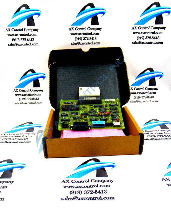
About the DS3800DCMB1D1C
The GE Printed Circuit Board DS3800DCMB1D1C features 1 40-pin connector and multiple EPROM modules. It also is populated with 4 indicator LEDs, 7 jumpers, and 1 20-pin connector. The 40-pin connector is the primary cable by which signals are transmitted from the board and also received by the board. The ribbon cable is approximately 8 inches long because it is engineered to plug into a connector that is only a short distance from the board when it is installed in the drive. A maximum of 40 separate signals can use the cable for transmitting and receiving.
The ribbon cable is easily damaged, so before you unplug it consider the following information. To unplug a ribbon cable, do not tug the cable because it will separate the ribbon cable from the connector. This is the case because the fine wires that comprise each connection are easily separated from the plastic connector. Instead, place your hand on the connector and pull it away from the board to disconnect it. To reconnect the ribbon cable, use one hand to hold the connector at the end of the ribbon cable and align it with the connector on the board. Press it into the connector when you are ready.
Once the board is installed and the drive is operational, you can view the LEDs to monitor the operation of the board. The IDs of the 4 LEDs are TXDA, RXDA, DTSA, and CDA. When the LEDs are flashing, it shows that processing is taking place.


