About the DS3800DDIB
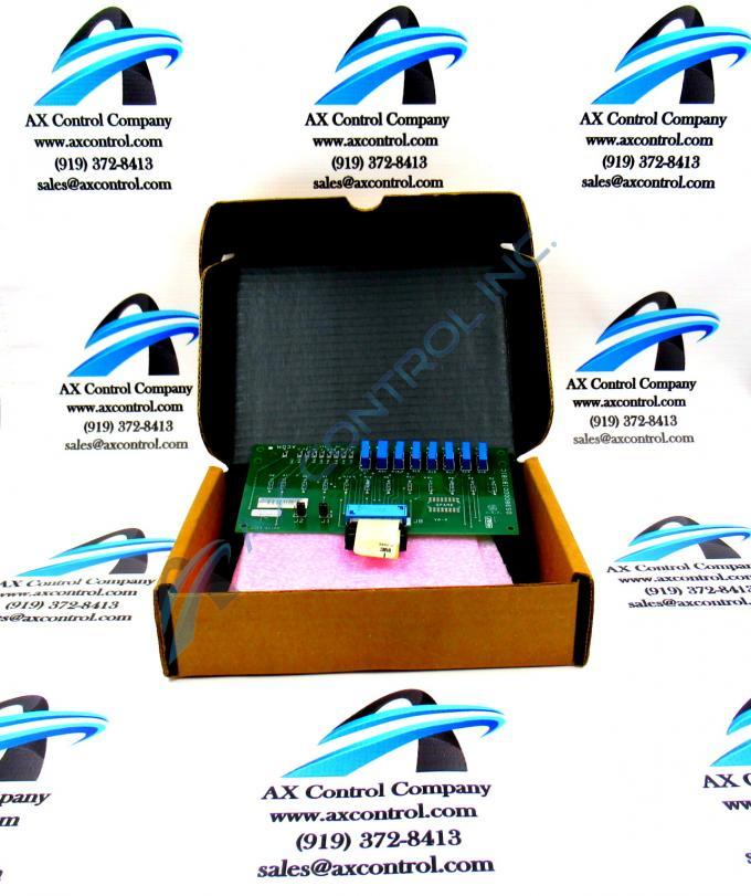
The GE Auxiliary Drive Interface Control Board DS3800DDIB features 8 trimmer resistors and 2 jumpers. The GE Auxiliary Drive Interface Control Board DS3800DDIB also is populated with 9 test points and 12 resistors. The IDs of the trimmer resistors are VCAL, VMET, MVC, IFC, IFM, IAC, TIA, and IAM. The trimmer resistors enable the installer to calibrate the board to the specific requirements of the drive. A small flat blade screwdriver is required to adjust the components. The use of a tester device is also required to make the adjustments. The installer will adjust the trimmer resistor and test multiple times until the desired results are indicated.
When the board is installed, it is best practice to record the settings of the circuits so that if the board must be replaced, the replacement board can be calibrated to the same specifications. Keep the settings with the other important information concerning the board. This includes the serial and model numbers, and the instructions for contacting customer support.
When you are ready to replace the board, have on hand a tester device that is calibrated for the testing being performed and inspect the probes to ensure they are in good condition. Also check to make sure they are compatible with the tester. Place the replacement board on a flat and clean surface and use the test points for testing the various circuits on the board. Each trimmer resistor is used to adjust a specific circuit. When all the circuits match the settings on the original board, you are ready to install the replacement board.


