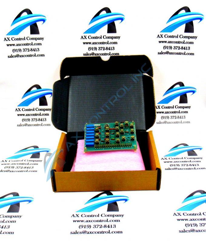
About the DS3800DDMA
The GE Div Multi Auxiliary Board DS3800DDMA features 20 single pin connectors and 7 trimmer resistors. It also is populated with terminals for attaching components, such as resistors or capacitors. The GE Div Multi Auxiliary Board DS3800DDMA serves as a daughter card that adds capacity or functionality to another board in the drive. The single pin connectors are comprised of connectors that can attach to matching pins attached to cables. The cables originate on another board or device on the drive. To attach a cable to a single pin connector, slide the pin into the single pin connector until it is fully seated. To remove a cable, pull it straight out of the single pin connector.
Some of the IDs assigned to the trimmer resistors are TSTVLT, DIV1, DIV2, and MULTI1. The trimmer resistors have an adjustment screw that a qualified installer or servicer can adjust to fine tune the performance of the board circuits. The installer or servicer can use a tester devices to gauge the performance of the circuit and adjust the trimmer resistor to improve the performance of the board.
You must consider the trimmer resistors when you replace the board because you must set the trimmer resistors on the replacement board to match the settings on the old board. First, when the original board is calibrated to your satisfaction, write down the testing results for each circuit and store them in a safe place. Then, before you install the replacement board, set the trimmer resistors so that the circuits provide the same testing results.


