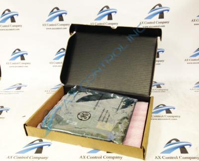
About the DS3800DECA
The GE LCI Exciter Control Board DS3800DECA features 1 20-pin ribbon cable and 5 trimmer resistors. The GE LCI Exciter Control Board DS3800DECA1B1B also is populated with 4 jumpers, 1 potentiometer, and 4 test points. Each jumper is assigned an ID that is silk screened on the surface of the board. The IDs are adjacent to each jumper on the board. The ID include the suffix BJ and is followed with a number. Some of the IDs are BJ1, BJ2, BJ3, and BJ4. When the original board is installed in the drive by an installer, the jumpers are used to configure the board to process information to obtain the results required for the drive. The full description of the jumpers is included in the printed material shipped with the board.
When you replace the board, it is not necessary to review the description of each jumper and review the full explanation provided in the written material. Instead, view the old board and document how each jumper is set. Each jumper has only two possible positions. The jumper can cover pins 1 and 2 or pins 2 and 3. While you wear a wrist strap move the jumpers on the replacement board to match the jumpers on the old board.
The GE LCI Exciter Control Board DS3800DECA1B1B is designed to provide maximum flexibility by the use of 1 potentiometer and 5 trimmer resistors to adjust the signal processing. You must configure the replacement board to provide the same signal processing as the old board before you install it.


