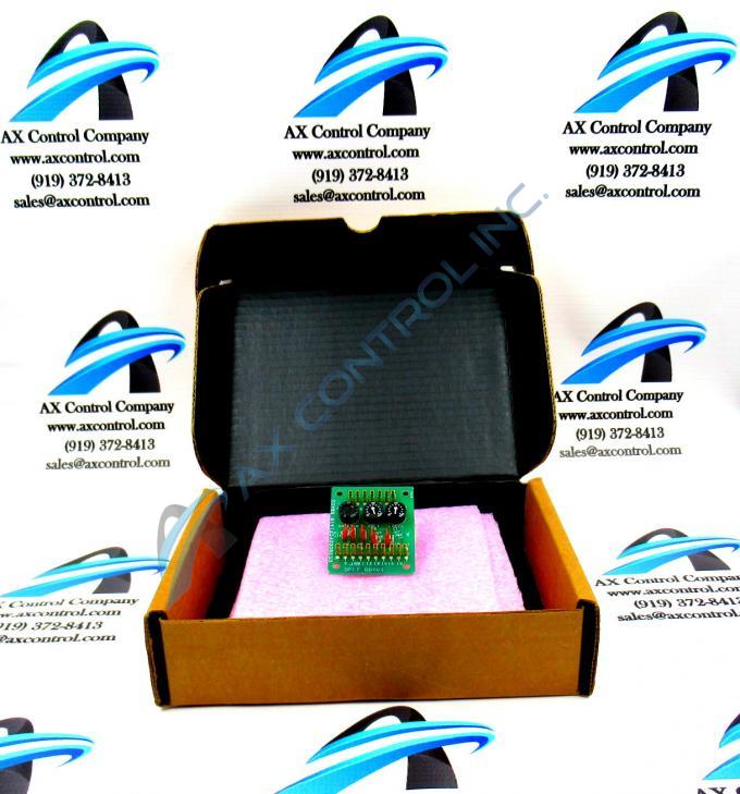
About the DS3800DFCF1A1B
The GE Firing Circuit Board DS3800DFCF1A1B features 17 single-pin connectors and 3 potentiometers for adjusting the current. The GE Firing Circuit Board DS3800DFCF1A1B also is populated with 7 jumpers.
Cables with the male single-pin connector attach to the single-pin connectors on the board. The connectors provide command signals to the board for processing. Some of the single-pin connectors transmit signals to other boards after processing. The written installation guide describes what signals to connect to the single-pin connectors. Once you have completed the cable connections, it is best practice to make notes on how the cables are attached to the single-pin connectors. If it is necessary to replace the board or remove it for repair, you can easily reconnect the single-pin cables.
Because the board might have a maximum of 17 single-pin cables connected to it, you must consider the proper method to route the cables in the interior of the drive. The 17 cables bundled together can block the flow of air through the interior of the drive. The drive uses the free flowing air to remove the heat generated by the components. Route the cables along the outside edge of the interior of the drive. This will allow the cool air to remove the heat. Also keep the cables from blocking the openings in the drive that allow the air to enter and exit the drive. The cool air enters the drive at the bottom and the heated air exits at the top of the drive.


