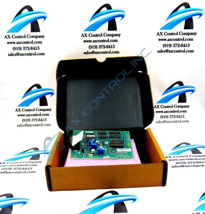
About the DS3800DFPH1D1B
The GE Circuit Board DS3800DFPH1D1B features 1 34-pin ribbon cable and 3 trimmer resistors. The GE Circuit Board DS3800DFPH1D1B also is populated with multiple test points and 1 transistor-transistor logic (TTL) component embedded on the board. The 3 trimmer resistors are also referred to as trimpots because they are a type of potentiometer. They enable the installer or servicer to fine tune the operation of the board for use in the drive. Because the board is not populated with jumpers, the trimpots are the only means of fine tuning the board. The trimpots are adjusted before they are installed. To adjust them, use a sharp bladed instrument to open the sealed static protective bag the board is packaged in. Wear a wrist strap and remove the board from the bag. Flatten the bag and lay out the board on top of the bag on a desk, table, or bench.
Have on hand a suitable testing unit to test each circuit and adjust the trimmer resistors for each circuit. Only a qualified installer or servicer will have the knowledge to properly fine tune the board. Another component of the board is a TTL and it serves as the interface logic between integrated circuits.
To install the board once the trimpots are adjusted, have on a hand a screwdriver and the 4 screws with which you plan to secure the board in the drive. Use 2 hands to pick up the board and carefully position it inside the drive. Use one hand to hold the screw in place and with the other hand tighten the screws.


