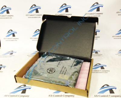
About the DS3800DGTA1C1D
This DS3800DGTA1C1D General Electric printed circuit board product offering was originally designed and produced specifically for their Mark IV Turbine Control System Series, as indicated in the brief product descriptions stored above on this DS3800DGTA1C1D personalized product page. The Mark IV Turbine Control System Series, as you may have been able to predict based just off of its full extended series name, has a set of specific applications in the management and control systems of General Electric-accepting gas and steam turbines; not yet the wide-reaching and alternative energy-including full range of functionality offered by later GE Mark Series iterations including but not limited to the Mark VI Turbine Control System Series. While this DS3800DGTA1C1D device's Mark IV Series' potential applications are somewhat restricted, the Mark IV Series is still able to garner a consistent level of demand on its greater automated industrial marketplace as it is one of the lastly-developed GE product series to feature the patented Speedtronic control system technology first seen with the advent of the Mark I Series in the mid to later 1960s.
Hardware Tips and Specifications
The GE Gas Turbine Board DS3800DGTA1C1D is designed for quick installation in the drive. The board features 1 hole in each corner. The board can be secured with screws into a location in the drive. The GE Gas Turbine Board DS3800DGTA1C1D also is populated with 1 20-pin ribbon cable attached to the board. The board is populated with 5 trimmer resistors and 6 wire terminals. The GE Gas Turbine Board DS3800DGTA1C1D is also populated with test points. The test points on the GE Gas Turbine Board DS3800DGTA1C1D are useful if 1 or more circuits on the board have stopped functioning. Because the board in not populated with indicator LEDs, you can use the test points to pinpoint the defect and plan how to resolve the issue. The GE Gas Turbine Board DS3800DGTA1C1D must be removed from the drive to use the test points. A final important note on this DS3800DGTA1C1D product's general hardware features; the DS3800DGTA1C1D Gas Turbine Control Board here could very well exist as the originally-developed product of its specific series given its mysteriously-formulated DS3800DGTA1C1D functional product number, but the DS3800DGTA1C1D functional product number seems to point to the addition of at least a singular revision rated at possible grades of C or D.
First disconnect the short 20-pin ribbon cable without damaging the cable. That is, do not tug the ribbon cable to disconnect it. Tugging the ribbon might damage the connections between the thin wires that carry the control signals and the connector that terminates the ribbon cable. Then, have on hand a screwdriver to remove the 4 screws. Use one hand to hold the screw and the other hand to turn the screwdriver. Make sure you have all 4 screws before you continue. Retrieve any screws that drop into the drive. If they are jammed against moving parts, they might damage the parts. The moving parts might cause injury if they jam, bend, break, or are ejected from the drive. While this DS3800DGTA1C1D printed circuit board's carious installation and replacement procedures are certainly important to remain cognizant of, their placement on this DS3800DGTA1C1D personalized product page here is truly entirely more reminiscent of this DS3800DGTA1C1D device's greater Mark IV Series' lack of originally-printed instructional manual documentation online than it is of their central importance. With this lack being identified, the DS3800DGTA1C1D functional product number itself can be turned to as a decent source of DS3800DGTA1C1D Board hardware component and component specification information, revealing this DS3800DGTA1C1D PCB's DGTA domestic location of original manufacture, normal Mark IV Series assembly version, and many other details through a series of specially-formulated functional naming segments.


