About the DS3800DLBA
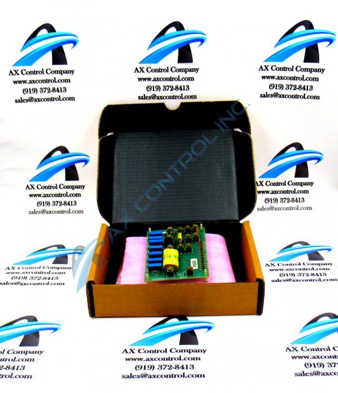
The GE Load Balance Auxiliary Board DS3800DLBA features 12 terminals for attaching additional components to the board, and 16 single-wire pin connectors. The GE Load Balance Auxiliary Board DS3800DLBA also is populated with 7 trimmer resistors and 1 transistor-transistor logic component embedded on the board. When the board is shipped from the factory, the 12 terminals are not populated with additional resistors or capacitors.
However, under some conditions additional components might be necessary to tailor the board. It is recommended that only authorised installers and servicers add components to the board. To add a component, have on hand a screwdriver and loosen the screw on top of the 2 terminals you plan to use. The terminals are part of various circuits. Don’t remove the screws but loosen them so that the lead wires can be inserted through them. Tighten the screws to secure the components when both lead wires are under the terminals.
The terminals protrude from the surface of the board and so care must be taken that you do not accidently knock the board against the drive or hit other boards in the drive.
The board also is populated with trimmer resistors that can be used to calibrate the circuits on the board. This is useful to tailor the board to process information specifically as required for the drive and how it is used at the site.
Have nearby a small screwdriver and use it to adjust the adjustment screws visible on the trimmer resistor. Use a tester to gauge how the circuit is changed as you turn the screw.


