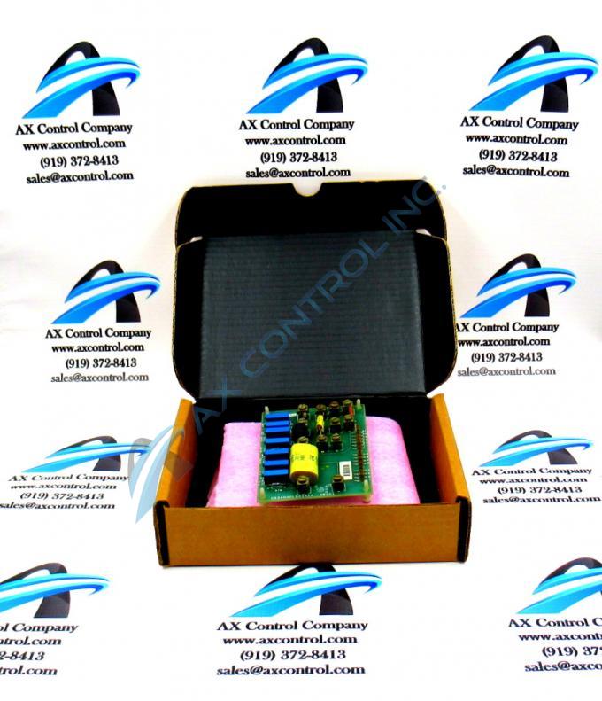
About the DS3800DLBA1A1A
The GE Load Balance Auxiliary Board DS3800DLBA1A1A features 12 terminals for attaching additional components to the board, and 16 single-wire pin connectors. The GE Load Balance Auxiliary Board DS3800DLBA1A1A also is populated with 7 trimmer resistors and 1 transistor-transistor logic component embedded on the board.
The 12 terminals on the board enable a qualified servicer or technician to add components to the board without modifying the design of the board. It is important that only qualified individuals add components because of the risk of damaging the board or other components in the drive. Also, the servicer and installer must know how to operate a testing device and how to calibrate it before hand.
The 12 terminals enable you to add components to various circuits on the board and so you must know to which circuit to add the component and which 2 terminals are connected to the circuit. You can add a maximum of 6 components between 2 terminals. To add the component, use a screwdriver to loosen the screws on the top of the terminals. Slide the lead wires into the terminals and tighten the terminal screws. Do not overtighten the screws.
Use a testing device to verify that the results you anticipated with the addition of the components are realized. It is important that you perform this activity when the board is removed from the drive and the servicer or installer is wearing a static protective wrist strap. Place the board on top of a static protective bag and work on a desk or table with a clean surface.


