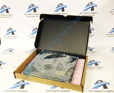
About the DS3800DMEA1D1C
GE has created the DS3800DMEA1D1C PCB or printed circuit board to integrate into the Mark IV Speedtronic series. This card works as an exciter control board. GE's Mark IV was designed with interconnected processors and built-in redundancies between chipsets that would shift communications and control as needed when one card experiences any kind of issue. In this way, the Mark IV has minimal downtime caused by electronics failure. The Speedtronic Mark IV performs such functions as air, fuel and emissions control, synchronization and voltage matching of the generator and the system, and protection of the turbine system against adverse operating conditions.
The DS3800DMEA1D1C has been factory drilled for mounting. It has one hole in each corner with one additional hole in the top left and bottom left corners. There are eight screw terminals and eight diodes on the DS3800DMEA1D1C. On the left edge are eight LEDs labeled tach loss/OS/OV/IOC/IOL/Field Loss/Alarm/Moving.
The DS3800DMEA1D1C has 21 ceramic, metal film resistors. There are fourteen adjustable resistors with 10-point hashes (0-100.) These are labeled IE Cal/Field loss/Min fld/IA cal/IR comp/CMPD/ % md/IOC Adj/Tol Adj/CEMF Cal/Overvolts/Spd Adj/ Slo Spd/Overspd.
The DS3800DMEA1D1C has one 50-pin male connector (marked 218A4637P5.) It has eleven TP rings. Nine are in the middle of the board and two are in the left bottom corner. It has eighteen jumper switches that are in a line down the center of the board. The DS3800DMEA1D1C also has one switch (labeled SW1.)
Technical support for the DS3800DMEA1D1C was originally provided by GE. Please refer to their data sheets and their manual published for this product for proper installation guidelines.


