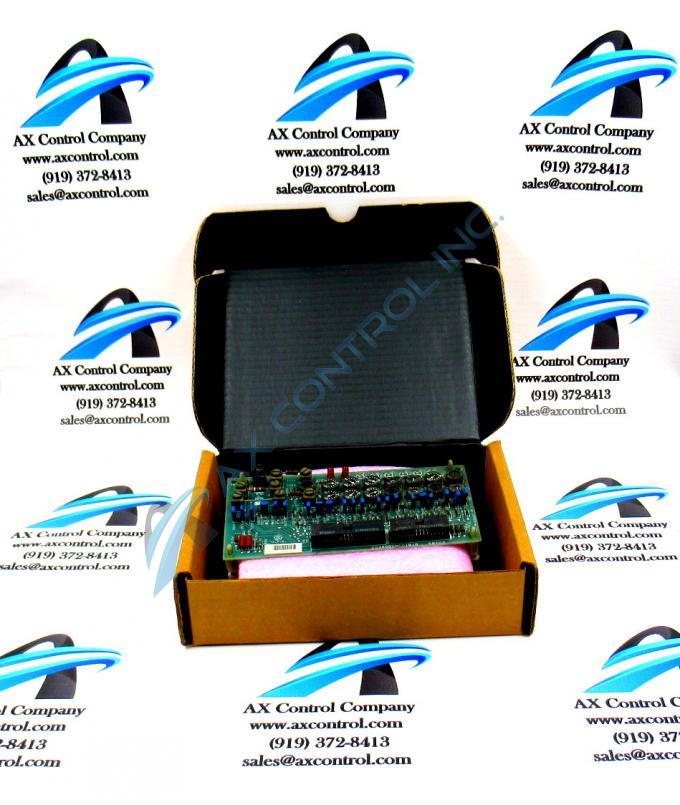
About the DS3800DMEC1C1C
The GE MD Exciter Control Board DS3800DMEC1C1C features 7 terminals for attaching additional components to the board, and 2 indicator LEDs. The GE MD Exciter Control Board DS3800DMEC1C1C also is populated with 14 potentiometers, 20 jumpers, 1 20-pin connector, and 1 34-pin connector.
The indicator LEDs are a useful tool for the operator to gain insight into the operation of the board. When the board is processing as normal the LEDs are not lit and no further intervention is required. However, if the one or both LEDs are lit, it indicates that a problem has occurred and the board is not processing as expected.
If that is the case, you can first use the diagnostic tools available on the drive. The tools provide information on the processing taking place in the drive. It also provides information on the motor and other moving parts. If any errors or warnings have occurred, the report would also list them. It would also list any trip conditions. A trip condition is a problem that will cause damage to the drive if not resolved. The trip condition causes the drive to shutdown automatically. Some trip conditions are excessive voltage supplied to the drive, exceeding the temperature threshold in the drive, and over loading the motor and moving parts.
The final method of pinpointing the cause of an error is to use the test points to test the specific circuits in the board. This can be accomplished by a qualified individual with a full function testing device.


