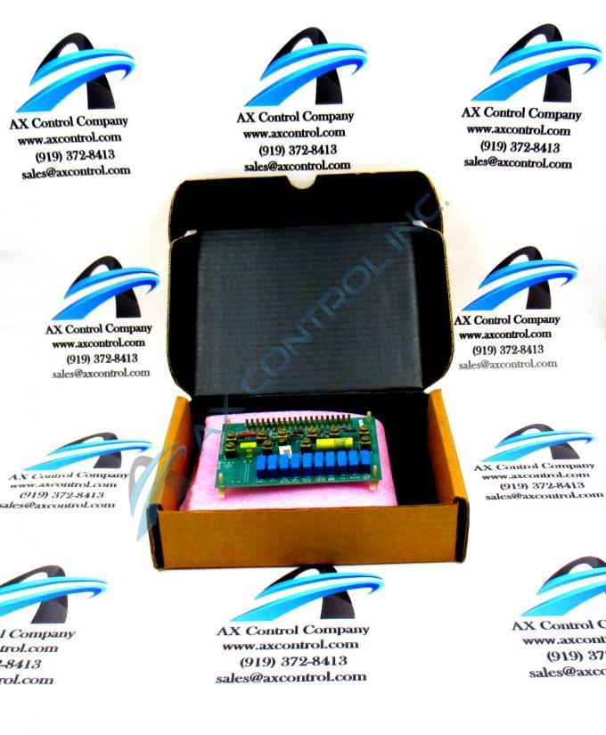
About the DS3800DMFA
The GE Motor Field Regulator Board DS3800DMFA features 10 terminals for attaching additional components to the board. The GE Motor Field Regulator Board DS3800DMFA also is populated with 10 trimmer resistors, 1 20-pin ribbon cable, multiple jumpers, and 11 resistors.
The resistors are permanently embedded on the board and they are assigned IDs that are printed in the surface of the board. The IDs assigned to some of the resistors are FOC1, FL1, FLD GAIN, FULL FLD, and IA.
The 20 single-pin connectors are typically connected to a device in pairs to complete an electrical circuit. One consideration is that when you plug the single-pin connector into the board, there a potential for damaging the surface of the board by scraping the pin across it. The best practice is to start by having a good view of the cable and the connector. This is accomplished by looking down on the board. Then, align the pin with the connector and press the pin into the connector. Make sure it is completely inserted into the connector.
The 20 cables attached to the single-pin connectors are bundled together and routed inside the drive. The cables might add up to a large bundle of cables and so care must be taken that they are routed so as to avoid causing problems. One potential problem is that the cables block air from moving through the drive. The air enters the drive at the bottom through vents and exits the drive through vents at the top. The air removes heat from the interior of the drive and exits the drive as hot air.


