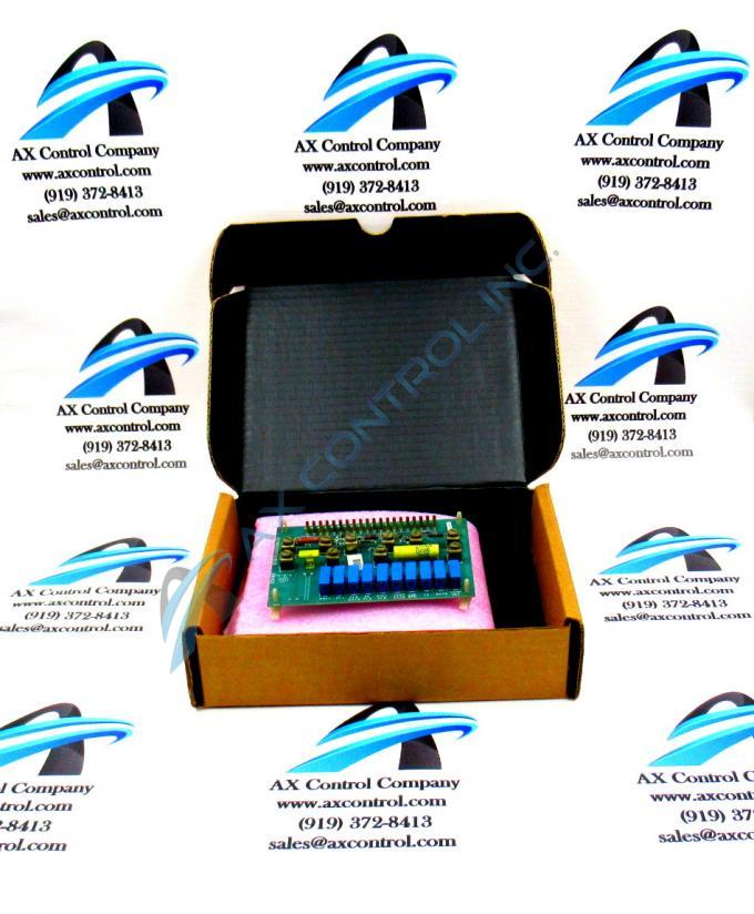
About the DS3800DMFA1B1B
The GE Motor Field Regulator Board DS3800DMFA1B1B features 10 terminals for attaching additional components to the board. The GE Motor Field Regulator Board DS3800DMFA1B1B also is populated with 10 trimmer resistors, 1 20-pin ribbon cable, multiple jumpers, and 11 resistors. The resistors are assigned IDs that are prefixed with the letter R. The ID is suffixed with a numeric value. Some of the IDs are R11, R16, and R13. The resistors vary in resistance and are installed to provide a specific processing result.
If additional components are required, you can use the terminals to add them to the board. Each set of terminals is associated with a particular circuit on the board. To use the terminals, refer to the installation instructions that shipped with the original board. It will describe the terminals and the circuits each terminal is part of. Only a trained technician should add components on the terminals because of the risk of damage to the board. Capacitors and resistors can be added to the board and only a highly knowledgeable individual will understand how to obtain a particular result.
Have available a flat-blade screwdriver to loosen the retention screw on top of the terminal. Do not remove the screw or the components of the terminal. Place the lead wire under the retention screws and tighten the screw. It is easy also to switch out the components because they are not embedded on the board. Loosen the screws and remove the component you want to remove and replace it with the new component.


