About the DS3800DOAA1A1B
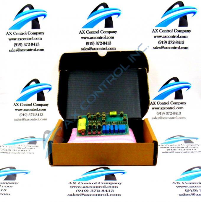
The GE Power Regulator Board DS3800DOAA1A1B features 6 trimmer resistors and 29 single-pin connectors. The GE Power Regulator Board DS3800DOAA1A1B also is populated with 20 terminals for attaching components.
The single-pin connectors can be used to connect 1 cable with a male pin connector attached to the end of it to the connector on the board. When you connect the cable, first identify the connector you want to connect the cable to. Each connector has an ID printed on the circuit board. The IDs are a numeric value ranging from 1 to 29. Align the male pin with the connector on the board and insert it until it is firmly attached. The information supplied with the board from the factory describes the purpose of each single-pin connector. Use that information to plan which cable you want to connect to the board.
Because of the high number of cables attached to the board, cable routing becomes a concern for a number of reasons. The cables attached to the single-pin connectors are signal cables which are sensitive to interference from power cables. Both types of cables are present in the board but they must be kept separated. To do this, the power cables must exit the drive along the side of the drive cabinet. The signal cables must be routed along the side of the drive and exit along the top of the drive. Also bundle the signal cables together and plan the routing so that they do not block the free flow of air.


