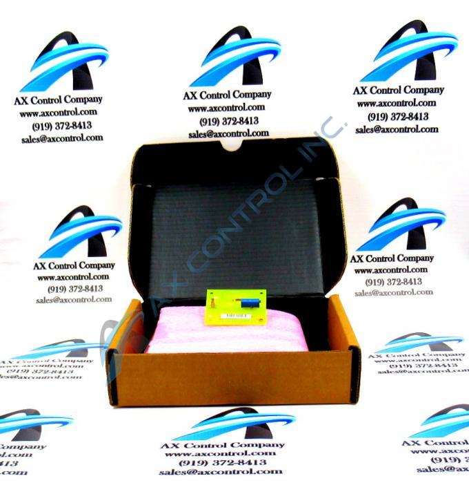
About the DS3800DSFC1A1A
This DS3800DSFC1A1A printed circuit board product offering from trusted automated industrial seller General Electric was originally designed and produced with a specific functional placement in their mark IV Turbine Control System Series in mind. As you may have been able to predict based off of its full series name inserted here before, the Mark IV Series that this DS3800DSFC1A1A printed circuit board and many other GE products belong to has a selection of specifically-identified applications in gas, and steam turbine assemblies; not quite yet featuring the bonus wind energy-geared functionality seen with later GE Mark product series iterations such as the Mark VI Turbine Control System Series. This DS3800DSFC1A1A device's Mark IV Series is still able to attract a consistent cult-like demand on its greater figurative automated industrial marketplace, however, as it is one of General Electric's final-developed Mark product series to make use of the patented Speedtronic control system technology seen first alongside the rollout of the initial Mark I product series in the later 1960s, again under General Electric.
Hardware Tips and Specifications
The interior of the drive is designed for multiple boards to be installed. The drive is designed with multiple spaces in which to install the GE Circuit Board DS3800DSFC1A1A. The board is engineered with 1 hole in each corner that will align with matching holes in the board rack in which the board is installed. Use a screwdriver to insert the screws in each corner and tighten them to provide a secure installation. If you overtighten the screws it might damage the board or allow the screws to pass through the board material. Before you install the board, the technician must decide if further adjustment is needed to be made to the trimmer resistor. Use a tester to measure the performance of the resistor trimmer and adjust it, if needed. If necessary, you can install the board and check the performance of the drive and if needed, you can remove the board and adjust the component. Once you have adjusted it, apply a small amount of a clear glue that will dry and prevent further adjustment of the screw. Only use an agent that can be peeled off and not damage the trimmer resistor. Plug a cable into the single-pin connector, if necessary. To connect the cable align the cable with the connector and slide it into place.
The GE Circuit Board DS3800DSFC1A1A is 2 inches in height and 3 inches in length. The board features 1 trimmer resistor, multiple capacitors, and 5 jumpers. The GE Circuit Board DS3800DSFC1A1A also is populated with 2 single-pin connectors and 10 resistors embedded on the board. These are all parts of a larger series of General Electric-formulated components designed to introduce this DS3800DSFC1A1A product's specific Mark IV Series functional role, which has unfortunately not been deemed as identifiable due to this DS3800DSFC1A1A product's lack of original instructional manual materials online given its now-obsolete legacy GE product series status. With this concerted lack of originally-produced instructional documentation existing, other avenues of DS3800DSFC1A1A hardware information must be identified; chiefly in the form of the DS3800DSFC1A1A functional product number that was specially-designed by General Electric to highlight a number of DS3800DSFC1A1A Board hardware component and component specification details through a series of consecutive functional naming segments. For instance, the DS3800DSFC1A1A functional product number begins with the dual-functioning DS3800 series tag that indirectly asserts the DS3800DSFC1A1A PCB's normal Mark IV Series assembly version as well as its domestic original manufacture origin.


