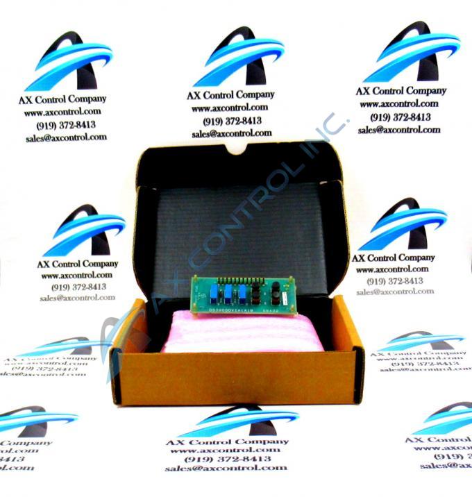
About the DS3800DVIA
The GE Circuit Board DS3800DVIA is 2 inches in height and 4 inches in length. The board features 12 single-pin connectors, 4 terminals for connecting additional components, and 2 resistors. The GE Circuit Board DS3800DVIA also is populated with 3 trimmer resistors.
The IDs of the trimmer resistors are R1, R2, and R3. When the board is delivered from the factory the trimmer resistors are set at a standard setting that is used by most installations. However, you might find that further configuration is required to achieve the processing you require. If that is the case, you must remove the board from the drive and place it on a clean flat surface. Only a qualified technician can adjust the settings of the trimmer resistors. The trimmer resistor is also called a trimpot because it is potentiometer. The technician must have a full-function tester on hand with probes that are designed for use with the tester.
The technician must refer to the specifications sheet for the board to understand which circuits the trimmer pots are part of. Use the small screw on the trimmer pot to adjust the resistance. When you are satisfied, it is a best practice to drop some clear glue or other agent on the screws to prevent the screws from being turned again. Also, choose a glue that can be easily peeled off if more adjustment is needed.
Reconnect the single-pin cables to the connector on the board. Bundle them together and route them to avoid blocking the airflow.


