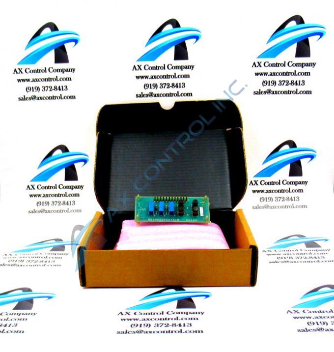
About the DS3800DVIA1A1B
The GE Circuit Board DS3800DVIA1A1B is 2 inches in height and 4 inches in length. The board features 12 single-pin connectors, 4 terminals for connecting additional components, and 2 resistors. The GE Circuit Board DS3800DVIA1A1B also is populated with 3 trimmer resistors.
The IDs of the resistors are suffixed with the letter R. The letter R is followed by a numeric value. For example, the IDs for the resistors are R2 and R4. The IDs for the trimmer resistors are also suffixed with the letter R. The letter R is followed by a numeric value. For example, the IDs for the resistor trimmers are R1, R3, and R5. The resistor trimmers are also called trimpots. The trimpots are potentiometers due to the small adjustment screw that enables the technician to adjust the resistance.
Each single-pin connector is used to connect 1 signal cable to the board. The board is populated with 12 signal-pin connectors. Due to the large number of single-pin connectors it is important that you attach the cables to the right connectors. The single-pin connectors have IDs that consist of 1 or 2 digit numeric values. Use the description of the single-pin connectors located in the installation instructions. Be sure to use the IDs to identify the right connector to attach a cable. When all the cables are attached, bundle them together and route them along the side of the drive interior. If any power cables are nearby, route them away from the signal cables. This reduces the opportunity for interference from the power cables.


