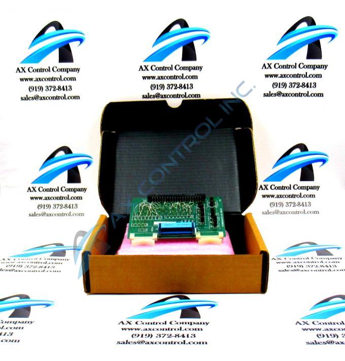
About the DS3800HACB1A1B
The GE Turbine Control Board DS3800HACB1A1B features multiple pins that are connected through fine wires wrapped around the pins. The GE Turbine Control Board DS3800HACB1A1B also is populated with 11 jumpers for configuring the board and 1 20-pin connector.
When the board is installed in the rack, the bottom edge is attached to the module connector at the rear of the board rack. The board is populated with a module connector that fits into the modular connector in the drive. When the retention levers are closed, the retention connectors are fully seated and the board receives power and signals through the module connector. Some of the signals are received by the board through the modular connector. They are processed by the board and prepared to be sent to other boards in the drive. Other signals are transmitted from the modular connector. When you open the retention latches and pull out the board the modular connectors pull apart and the connections are lost.
The 20-pin connector is located on the top edge of the board between the retention levers. If you plan to connect a 20-pin ribbon cable, first install the board in the rack and close the retention latches. Then, plug the connector into the 20-pin connector. When you remove the board, before you open the retention latches, use 1 hand to unplug the ribbon cable and move it away from the board. The ribbon cable is easy to break by putting strain on the connector. The fine wires that attach the connector to the cable are fragile.


