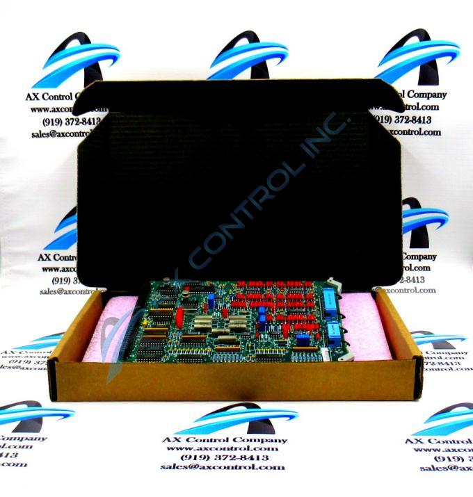
About the DS3800HAFA1D1E
The GE Regulator Board DS3800HAFA1D1E features a modular connector for attachment to a drive and retention levers to hold the board in the drive. The GE Regulator Board DS3800HAFA1D1E also is populated with 11 jumpers, and 4 trimmer resistor components. The board also has 1 20-pin connector and 1 34-pin connector.
The 20-pin connector and 34-pin connectors are located on the top edge of the board between the retention levers. They attach to ribbon cables that provide a means for signals to be received by the board for processing. They also enable signals to be sent to other boards after processing. The best practice is to connect the 20-pin and 34-pin ribbon cables after the board is installed in the board rack. This is because the ribbon cables can easily be broken if stress is placed on the ribbon cable and the connector on the end of the ribbon cable. The fine strands of wire that connect the cable to the connector are easily pulled from the connector. The signal is lost for any connection that is damaged. If the board is secure in the rack, the ribbon cables will not be subject to stress from moving the board.
Also, the ribbon cables must be routed properly to avoid interference from power cables in the drive. Route the ribbon cables along 1 side of the drive and route any power cables along the other side of the drive. Limit the exposure of the signal cables to the power cables as much as possible.


