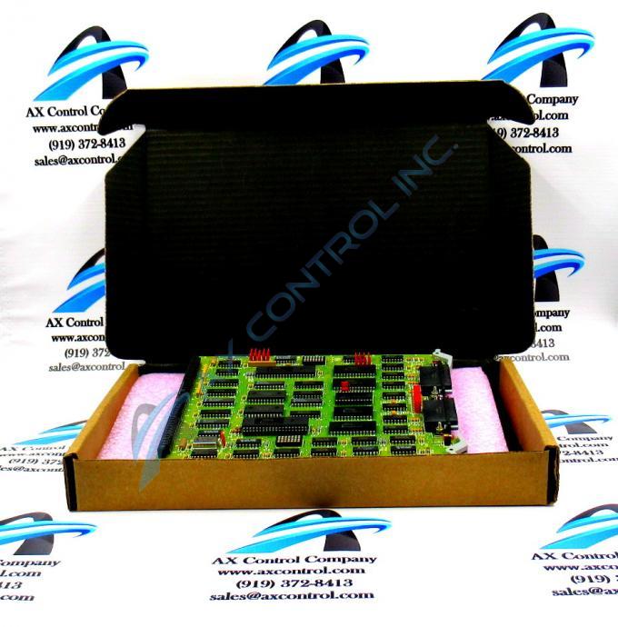
About the DS3800HCMA1E1G
The GE Dual Communications Control Board DS3800HCMA1E1G features a modular connector for attachment to a drive and retention levers to hold the board in the drive. The GE Dual Communications Control Board DS3800HCMA1E1G also is populated with 20 jumpers, and 1 amber and 2 red indicator LEDs. The board also has 2 34-pin connectors, and multiple capacitors.
Hardware Tips and Specifications
The jumpers embedded on the GE Dual Communications Control Board DS3800HCMA1E1G provide the means to configure the behavior of the board. Each jumper includes 2 positions that define how the board processes the signals it receives from other boards and components in the drive. It also configures how the board processes signals that it transmits to other boards and components. The jumpers must be set before the board is installed in the drive. This is because when the board is installed, it is sandwiched between other boards and the technician loses access to the jumpers. The board is designed to enable the operator to view the 3 indicator LEDs and also have access to the 2 34-pin connectors while installed.
When the original board is installed in the drive, the installer must review the information about the jumpers and confer with the site operators about how to configure the board for use at the site. It is best practice to record the jumper settings and keep the record with the other important information about the board. It is helpful if you must replace the board or want to use the same configuration on another board.


