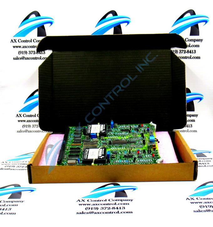
About the DS3800HCVA1H1F
The GE Digital to Analog Output Board DS3800HCVA1H1F features a modular connector for attachment to a drive and retention levers to hold the board in the drive. The GE Digital to Analog Output Board DS3800HCVA1H1F also is populated with 14 jumpers, and 2 amber indicator LEDs. The board also has 3 connectors accessible from the front of the board, and 4 trimmer resistors.
The jumpers are the primary method for a technician to configure the board to operate most effectively in a drive. The manual supplied with the board contains information about the jumpers and describes how the jumper positions can change the board processing. The jumpers have 2 positions and changing the position changes the board configuration. The jumpers have 3 pins. Change the pins that the jumper covers to change the configuration. The jumper can cover pins 1 and 2 or pins 2 and 3. When the board is manufactured, the jumpers cover the default configuration. The default is usually the standard or typical configuration. However, it can easily be changed if needed.
Use your fingers or a small set of pliers to move the jumper. Pull up on the jumper to remove it from the 2 pins it covers. Then, align it with the 2 pins you want to cover. Gently slip it over the pins. However, do not bend the pins or break them off the board.
The IDs of the jumpers are 2 or 3 position identifiers. The suffix is always the letter J. The remainder of the ID is a 1 or 2 position numerical value. The IDs are printed on the board for easy identification.


