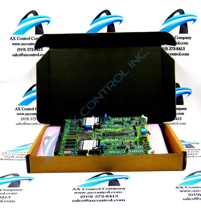
About the DS3800HCVA1J1G
The GE Digital to Analog Output Board DS3800HCVA1J1G features a modular connector for attachment to a drive and retention levers to hold the board in the drive. The GE Digital to Analog Output Board DS3800HCVA1J1G also is populated with 14 jumpers, and 2 amber indicator LEDs. The board also has 3 connectors accessible from the front of the board, and 4 trimmer resistors.
Hardware Tips and Specifications
When you install the GE Digital to Analog Output Board DS3800HCVA1J1G, the module connector at the end of the board slides first into the board rack. The module connector meets a module connector in the rack. Use 2 thumbs to gently press the board into the module connector. You will note that the levers are positions to be engaged. Press down of the levers to lock the board in the rack. When the board is installed properly, the 2 LEDs are visible to the operator. They are an easy and quick method for the operator to monitor the operation of the board. The LEDs flash when the board is processing information. When the LEDs are off for an extended period of time, it indicates that the board has stopped processing or has an intermittent problem.
If that happens, it is best practice to turn off the power to the drive and wait 30 seconds for all power to exit the drive. Then, release the retention levers and pull the board slightly out of the rack. Wait several seconds and return the board to the rack and press it back into the modular connector and close the retention levers. This DS3800HCVA1J1G Digital Card device here is likely not actually General Electric's originally-developed device of its specific functional role. as that would in fact have to be introduced as the DS3800HCVA Parent Digital Card not making use of this DS3800HCVA1J1G Digital Card product's numerous significant revisions.


