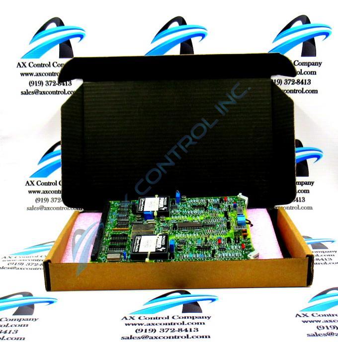
About the DS3800HCVA1J1H
The GE Digital to Analog Output Board DS3800HCVA1J1H features a modular connector for attachment to a drive and retention levers to hold the board in the drive. The GE Digital to Analog Output Board DS3800HCVA1J1H also is populated with 14 jumpers, and 2 amber indicator LEDs. The board also has 3 connectors accessible from the front of the board, and 4 trimmer resistors.
The trimmer resistors are often called trimpots. This is because they have an adjustment screw and are potentiometers. The screws adjust the resistance supplied by the component. A qualified servicer can perform the adjustment. The servicer must have a full featured testing device to monitor the voltage while adjusting the screw. Once the proper adjustment is made, cover the screw with a few drops of a liquid that quickly hardens and prevents the screw from moving. The liquid does not harm the components and can be peeled off to allow a servicer to make more adjustments. This might happen if the board is installed in another drive or if additional components are added to the drive.
Never force the board into the rack or force the retention levers. If the board doesn’t easily slide into the rack, reposition the board over the modular connector and gently press down. If aligned properly, the modular connector will slide into the matching connector in the rack.
When the drive is powered on, the LEDs on the board will light for several seconds. This serves as a test to prove the LEDs are functional.


