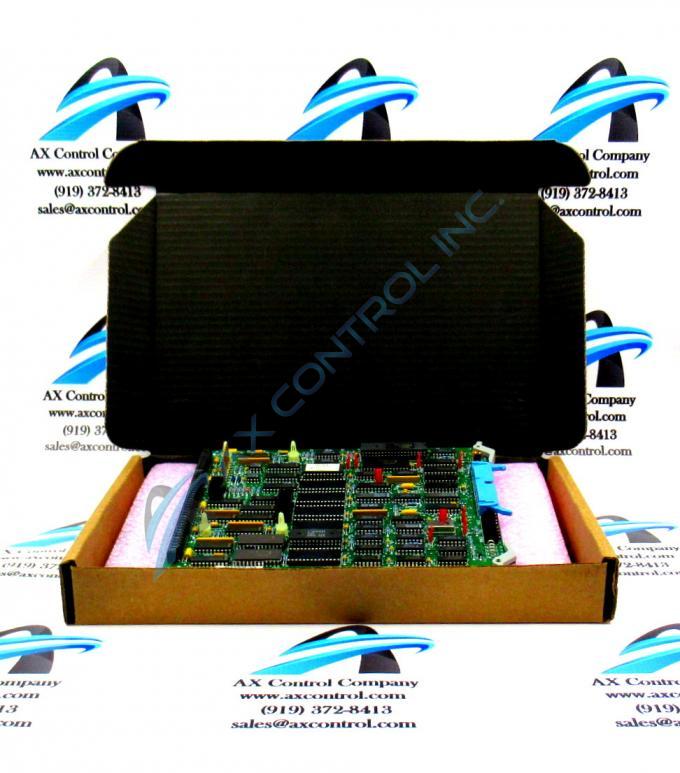
About the DS3800HFPC1L1H
This DS3800HFPC1L1H printed circuit board product offering from General Electric was originally designed and produced specifically with their Mark IV Turbine Control System Series in mind. The Mark IV Series that this DS3800HFPC1L1H product belongs to, as encouraged through its full extended series name, has a series of specific applications in the control and management systems of General Electric-compatilble gas and steam turbine automated drive assemblies; not yet extending to the full functionality enjoyed by the Mark VI Series encapsulating alternative energy-geared wind turbine settings as well. This DS3800HFPC1L1H printed circuit board or PCB for short's greater Mark IV Series is still viewed as quite the desirable General Electric product series on its greater figurative automated industrial promotional community however, as it is one of General Electric's lastly-developed Mark product series to incorporate the company's trusted Speedtronic control system technology into a range of its different offerings.
Hardware Tips and Specifications
The GE Function Processor Board DS3800HFPC1L1H features a modular connector for attachment to a drive and retention levers to hold the board in the drive. The GE Function Processor Board DS3800HFPC1L1H also is populated with 8 jumpers, and multiple capacitors. The board also has 1 40-pin connector that is accessible from the front of the board. It also has standoffs for attaching a daughter card. Another component on the board is a transistor to transistor logic (TTL) device. It serves as the interface logic between integrated circuits. This DS3800HFPC1L1H product likely mounts in the Mark IV Turbine Control System Series' standard VME Rack Installation Assembly, given its base printed circuit board's possession of two plastic retention clips for insertion in this style of mounting assembly.
The last step in installing the board is to connect a ribbon cable to the 40-pin connector on the board. The connector is accessible to the installer when the board is installed in the rack. The connector is located between the 2 retention levers. They secure the board in the rack and firmly connect the 2 modular connectors. 1 modular connector is embedded on the board. The other is located inside the drive at the rear of the board rack. When you insert the board in the rack, the 2 modular connectors meet and form a connection. When you lock the retention levers, the modular connectors are firmly seated. To install a ribbon cable, hold the plastic connector at the end and leave slack in the ribbon cable. Align it with the connector on the board and press it into the connector. Look for space in the connection and press the 2 connectors together again. Pull the cable out by holding the plastic connector. If you pull out the ribbon cable by holding the ribbon cable, you might damage the ribbon cable. While this DS3800HFPC1L1H device's various installation and replacement procedure are certainly important to remain cognizant of before making any ultimate purchase decision, their presence on this DS3800HFPC1L1H personalized product page here is truly more reminiscent of this DS3800HFPC1L1H product's lack of originally-printed instructional manual materials online, With this being the case, the DS3800HFPC1L1H functional product number can be utilized at least to identify this DS3800HFPC1L1H PCB's:
- Domestic original manufacture location
- Normal Mark IV Series assembly version
- HFPC functional product acronym
- Group one Mark IV Series product grouping
- Unique revision history


