About the DS3800HIOA1B1B
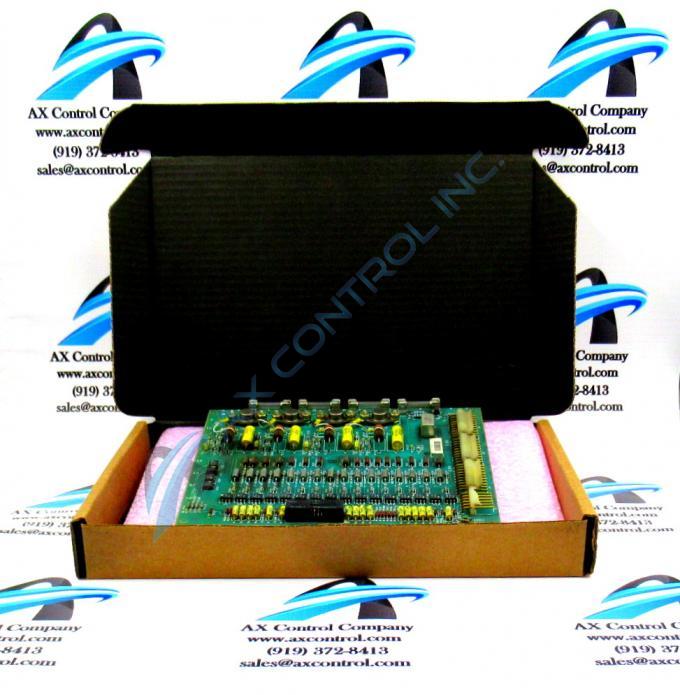
The GE Input Isolator Board DS3800HIOA1B1B features a hole in each corner for installing the board with screws. The GE Input Isolator Board DS3800HIOA1B1B also is populated with a microprocessor and multiple erasable programmable read-only (EPROM) modules. The board has 1 34-pin connector that is accessible from the edge of the board. It also is populated with test points.
A ribbon cable is attached to the 34-pin connector. The 34 separate signals it carries are commands the board sends to other boards for processing. Other signals are received by the board. Those signals are processed by the board. The ribbon cable requires special consideration because it is a wide cable and can block air from moving through the drive. Proper cable routing can help maintain the airflow. Route the cable along the outside edge of the drive interior and avoid blocking air from reaching components and other boards.
The ribbon cable attaches to the board through a connector on the end of the cable. It doesn’t have a sturdy connection to the ribbon cable and can easily be pulled out of the ribbon cable or lose connections. Always maintain some slack in the ribbon cable so that the cable is not strained or pulled. Never pull the ribbon cable out by tugging the ribbon cable. Instead, hold the connector and gently remove it from the connector.
When you are connecting the ribbon cable and installing the board, protect the board from static electricity build up. Wear a wrist strap to protect the components from damage.


