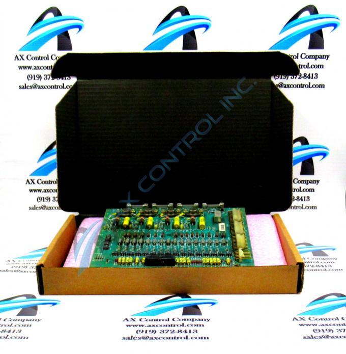
About the DS3800HIOA1B1D
The GE Input Isolator Board DS3800HIOA1B1D features a hole in each corner for installing the board with screws. The GE Input Isolator Board DS3800HIOA1B1D also is populated with a microprocessor and multiple erasable programmable read-only (EPROM) modules. The board has 1 34-pin connector that is accessible from the edge of the board. It also is populated with test points.
The GE Input Isolator Board DS3800HIOA1B1D is mounted on a wall and the installation procedure involves several steps. A mounting plate is included as the back panel of the drive. Specific mounting hardware is required to install the mounting plate. This includes bolts and other hardware, depending on the construction of the wall. You must also have the signal cables prepared for the drive. This includes networking cables and other types that will control the drive. The signal cables must be located near the drive so that the cables can be wired directly to the drive. Power supply cables must have emergency shut off devices installed near the drive. The power cable must have the voltage necessary to power the drive. Route the signal cables well away from the power cables due to the interference that can occur in the command signals. The power supply cables emit interference that is picked by the signal cables. If proper cable routing is not possible, shielded signal cables can eliminate or greatly reduce the interference.
If you plan to use fiber optic cables, you can route them without regard to the power cables. This is because fiber optic cables cannot pickup the power cable interference.


