About the DS3800HIOD1G1E
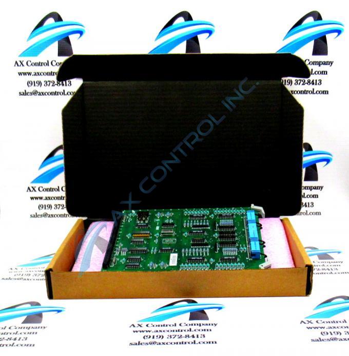
The GE Digital I/O Board DS3800HIOD1G1E is designed for quick installation in the drive. The board features a modular connector on 1 end and retention levers on the other end. The GE Digital I/O Board DS3800HIOD1G1E also is populated with 2 10-pin connectors and 1 40-pin connector located between the retention levers making them accessible from the front of the board. It also is populated with 6 jumpers.
The GE Digital I/O Board DS3800HIOD1G1E can be configured for use in many different environments. The configuration is performed by the installer with input provided by the site operators and engineers. The board comes from the factory with a default configuration. This is a standard configuration used in most work environments. However, the 6 jumpers can be changed to suit the specific needs of the environment. The definitions of the jumpers is included in the installation and service document included with board from the factory. Review the information and if you decide to change a jumper, place the board on a workbench or other workspace.
Wear a wrist strap and locate the jumper you want to change. The jumper IDs are prefixed with J. The prefix is followed with a numerical value. For example, J1, J2, and J3 are some jumper IDs. You use your thumb and forefinger to lift the jumper from the jumper pins. Then, gently place the jumper over the new set of pins. Work slowly so that you do not bend the pins or break them off the board.


