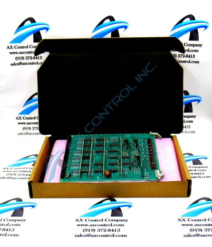
About the DS3800HLEA1B1B
The GE Logic Element Board DS3800HLEA1B1B features a modular connector for attachment to a drive and retention levers to hold the board in the drive. The GE Logic Element Board DS3800HLEA1B1B also is populated with 10 indicator LEDs that are viewable from the front of the board and 3 jumpers. The board is populated with resistors and capacitors. It also features dividers to direct the airflow over the components.
Another component on the board is a transistor to transistor logic (TTL) device. It serves as the interface logic between integrated circuits.
The indicator LEDs are located on the front edge of the board between the retention levers. This makes them visible to the operator while the drive is in operation. The LEDs are red in color and they provide an indication of the activity of the board. Each LED is associated with a board function. And the LEDs flash while activity is taking place. When activity has stopped, the LEDs stop flashing. When the LEDs have stopped flashing either activity has stopped and the board is healthy or a problem has occurred with the board function. If the operator is unsure of the board condition, the diagnostic program is available to provide information. The diagnostics are available from the control panel. A report is generated that provide information on the health of the drive and provides details on the GE Logic Element Board DS3800HLEA1B1B. If any errors or trip condition are included in the log, they are listed in the diagnostic report.


