About the DS3800HLIA1B1D
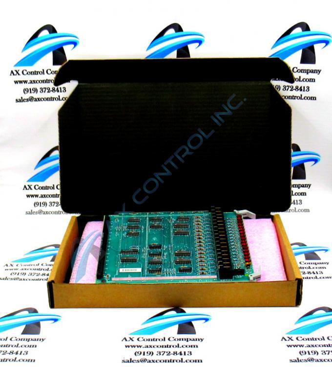
The GE Div Multi Auxiliary Board DS3800HLIA1B1D is designed for quick installation in the drive. The board features a modular connector on 1 end and retention levers on the other end. The GE Div Multi Auxiliary Board DS3800HLIA1B1D also is populated with 15 red indicator LEDs and 1 amber LED which are visible from the front of the board.
The indicator LEDs on the GE Div Multi Auxiliary Board DS3800HLIA1B1D are useful for obtaining a quick understanding of the health of the board. The LEDs are situated between the retention levers on the front of the board. This makes them viewable while the drive is in operation. The amber LEDs is lit when the board is receiving power and has passed all the startup diagnostic tests. The red LEDs are lit when processing activity is occurring on the board. Each LED indicates activity in 1 circuit on the board. A description of the LEDs is located in the written material supplied with the board. It describes the LEDs and which circuits the LEDs are associated with. When you view the red LEDs and they are flashing, it indicates that activity is normal and no further action is required.
If the LEDs are not flashing an error might have occurred. To find a resolution, the first step is to remove all power from the drive. Then, lift up on the retention levers to disconnect the board from the modular connector at the rear of the board rack. Wait a few seconds and return the board to the board rack and press down on the retention levers to lock it in place. Then, return power to the drive and resume processing. This might resolve some signal or processing errors by giving the board a restart.


