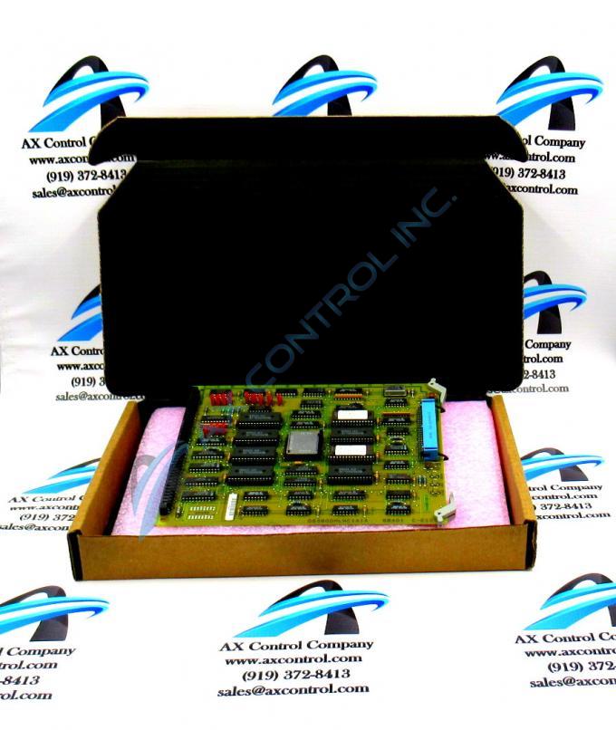
About the DS3800HLNC1B1B
The GE Network Control Board DS3800HLNC1B1B is designed for quick installation in the drive. The board features a modular connector on 1 end and retention levers on the other end. The board is populated with 1 40-pin connector between the retention levers. The GE Network Control Board DS3800HLNC1B1B also is populated with a microprocessor and 1 amber indicator LED.
Hardware Tips and Specifications
The board is also populated with 8 sockets for electrically erasable programmable read-only memory (EEPROM) modules and 21 jumpers. Because the GE Network Control Board DS3800HLNC1B1B can have a maximum of 8 EEPROM modules, care must be taken that you install them in the right socket on the replacement board. Each socket is assigned an ID that is printed on the surface of the board. When you are ready to move the modules to the new board, move each module individually. That is, remove 1 module from a socket and note the ID assigned to the socket. Then, locate the same socket on the replacement board. Align the module over the socket and press it into the socket. Then repeat the process for all the modules.
Another task is to set the jumpers on the replacement board. The jumpers are set when the first board is installed. Engineers and operators supply input about the best configuration to use for the board. To configure the replacement board you can access the written record of the jumper settings and set the jumpers to match. Use 1 hand to lift the jumper off the pins and move it over the pins you want to cover.


