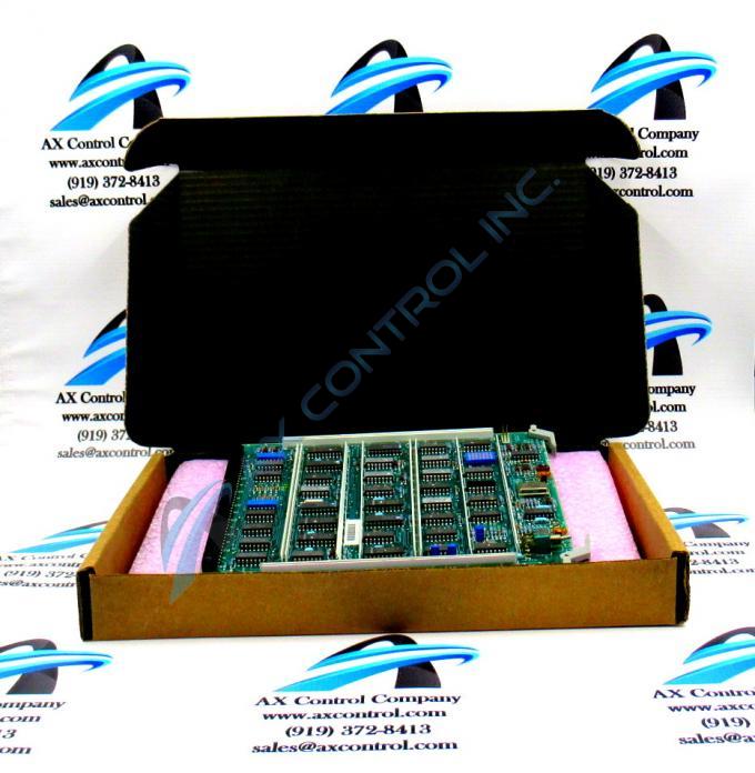
About the DS3800HPBC1A1B
The GE Parallel Line Buffer Board DS3800HPBC1A1B is designed for quick installation in the drive. The board features a modular connector on 1 end and retention levers on the other end. The GE Parallel Line Buffer Board DS3800HPBC1A1B also is populated with 1 red indicator LED and 2 amber LEDs which are visible from the front of the board. The board also is populated with 3 trimmer resistors, and multiple capacitors.
Another component on the board is a transistor to transistor logic (TTL) device. It serves as the interface logic between integrated circuits. The trimmer resistors are adjustable resistors. They can be adjusted to improve the performance of the drive. The trimmer resistors are called trimpots because they are potentiometers. That is, the small screws can be turned to change the resistance of the component. To use the trimpot, have on hand a full function testing device. Place the board on a static resistant mat that is free of dirt and dust. Keep the board away from objects that scratch the surface or bottom of the board. Any scratches can damage the board. Use the testing device to monitor the trimpot and turn the screw until the desired resistance is reached.
When finished you can drop an electrical glue on the screw. It hardens and can prevent the screw from being turned accidently. However, the glue can be peeled off to allow further adjustment. This might be necessary if the board is installed in another drive.


