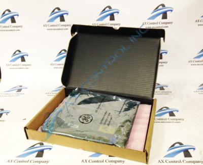
About the DS3800HPLA1A1A
The GE Panel Interface Board DS3800HPLA1A1A is designed for quick installation in the drive. The board features 1 hole in each corner. The board can be secured with screws. The board is populated with 1 40-pin connector embedded on the board. The GE Panel Interface Board DS3800HPLA1A1A daughter card also is populated with 3 red indicator LEDs. The board is also populated with 2 sockets for electrically erasable programmable read-only memory (EEPROM) modules, 7 jumpers, and 2 trimmer resistors.
The daughter card on the GE Panel Interface Board DS3800HPLA1A1A comes from the factory with a capacitor installed between 2 of the wire terminals. The wire terminals enable the technician to add components to an existing circuit. The capacitor stores current during normal processing. The capacitor stores high-voltage current. When a signal is received, the capacitor releases the high-voltage current. The storage and release cycle repeats many times during normal processing.
The technician can also add wires between the wire terminals. The wires must be a proper gauge and have insulation. The ends of the insulated wires are bare to carry the signals between the terminals. Insert 1 end of the wire under the terminal screw and tighten it with a screwdriver. Then insert the other bare end into the other wire terminal and tighten it with the screwdriver. You can use a testing device to ensure the wire gives the results you need. Refrain from using wires that are too long and have excessive slack. This can interfere with the air flow inside the drive.


