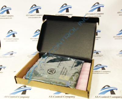
About the DS3800HPLA1G1E
The GE Panel Interface Board DS3800HPLA1G1E is designed for quick installation in the drive. The board features 1 hole in each corner. The board can be secured with screws. The board is populated with 1 40-pin connector embedded on the board.The GE Panel Interface Board DS3800HPLA1G1E daughter card also is populated with 3 red indicator LEDs. The board is also populated with 2 sockets for electrically erasable programmable read-only memory (EEPROM) modules, 7 jumpers, and 2 trimmer resistors.
The trimmer resistors that populate the GE Panel Interface Board DS3800HPLA1G1E provide a means to adjust the board to the requirements of the drive and the processing environment. The trimmer resistors are potentiometers because they can be adjusted. They are sometimes called trimpots. They have a screw on the top edge that the servicer can turn to make the resistance adjustment. You need a well calibrated tester device to make a precise adjustment. The servicer will turn the trimpot screw and monitor the resistance on the testing device. When the precise adjustment is complete, a liquid is available that will harden over the screws and prevent the screw from being turned. The liquid can be peeled off, if need be. This means that if the board is removed from the drive and placed in a new drive in another location, the trimpots can be adjusted for the new environment.
If the board is moved to a new environment, it might also be necessary to move the jumpers. This gives the installer the opportunity to configure the board for use in the new drive.


