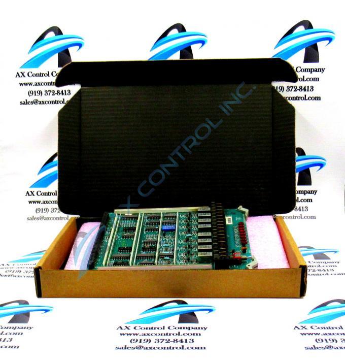
About the DS3800HRRA
The GE Relay Output Board DS3800HRRA is designed for quick installation in the drive. The board features a modular connector on 1 end and retention levers on the other end. The board is populated with 8 red indicator LEDs and 1 reset toggle switch. The analog/digital converter is a component embedded on the board. It converts the analog signals to a digital format. The digital format is used for signal processing throughout the drive. The board is also populated with 1 amber indicator LED.
The operator can monitor the board by viewing the indicator LEDs. The red indicator LEDs each shows the activity of 1 circuit. When the red LEDs flash, it indicates that activity is taking place. If 1 or more LEDs remain off, it might indicate that the circuit is defective. This is caused by several reasons but the first troubleshooting resource is the reset toggle switch. It is located at the front of the board which allows the operator to access the switch while the drive is active. The use of the switch is limited to trained servicers. This is due to the high-voltage current present in the drive when it is powered on. Only individuals who understand the danger from serious injury caused by high-voltage electricity should work inside the drive when power is on.
The switch when used will halt processing in the board for approximately 30 seconds. This will cut off control signals from being transmitted to the board and also halt control signals from being transmitted from the board. If the signals have become out of sequence, the reset action might resolve the issue and enable the board to restore full function.


