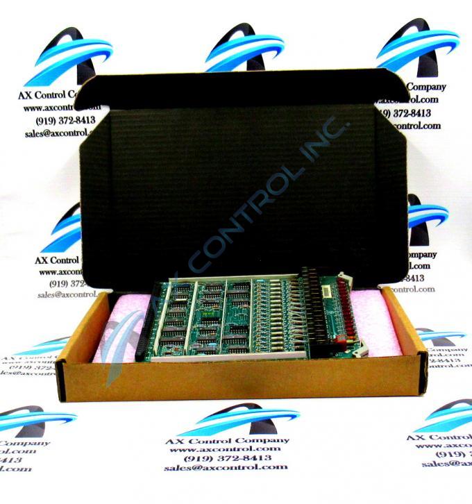
About the DS3800HSCD1F1D
The GE High Level Non-Isolated Input Board DS3800HSCD1F1D features a modular connector on 1 end and retention levers on the other end. The board is populated with a multiple capacitors. The board is populated with multiple transistor-transistor logic devices. The GE High Level Non-Isolated Input Board DS3800HSCD1F1D is also populated with 16 red indicator LEDs and 1 amber indicator LED. The board also has 1 socket for electrically erasable programmable read-only memory (EEPROM) modules. The board is also populated with 3 trimmer resistors.
The red indicator LEDs are located along the front of the board. The retention levers are located adjacent to the red indicator LEDs. The amber indicator LED is also located adjacent to the retention levers. All the indicator LEDs are visible to the operator while the drive is processing. The red indicator LEDs are on when activity is taking place on the board. Each red LED is assigned an ID printed on the board. The red LEDs are each associated with an individual circuit. When the circuit is active the LED flashes. When the LED is off, it indicates that activity is not taking place on the circuit.
If the amber LED is on, it indicates that a problem has occurred with the board. One course of action is to use the diagnostic programs to identify the problem. The diagnostic program generates a list of all errors that have been recorded for the drive. It also lists the trip conditions. The diagnostics also provide specific information about the components in the drive.


